
Cross-Hole Brush UFIBER® – Technical Information & Application Guide
UFIBER® Cross-Hole Brushes are ceramic-fiber tools for controlled deburring and finishing of internal bores and cross-hole intersections. During rotation, the fibers expand under centrifugal force to contact the internal surface and intersecting edges.
Suitable for machining centers, CNC equipment and robotic systems across steel, stainless steel, aluminum, heat-resistant alloys, cast iron, composites and resin materials.
Features
Centrifugal Expansion
Fibers spread outward during rotation to contact the internal bore and cross-hole edges.
Internal Burr Removal
Designed for fine burr removal at internal cylinder surfaces and intersecting holes.
Residue & Scale Removal
Helps remove cutting particles, processing residue and black scale.
Ceramic Cutting Edges
Ceramic fibers provide cutting action through exposed abrasive edges.
Wide Material Coverage
For steel, stainless steel, aluminum, cast iron, composites and resin materials.
CNC & Robotic Ready
Suitable for machining centers, CNC equipment and robotic systems.
Cross-Hole Brush Product Range
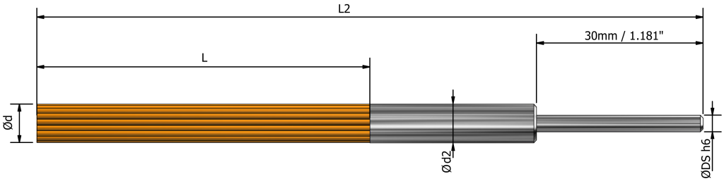
| SKU# | Description | Grit size | Ødmm / inch | Lmm / inch | Ød2mm / inch | L2mm / inch | ØDSmm / inch | Weightgram | Maximum spindle speedmin⁻¹ | Suitable pilot-hole diameter | |
|---|---|---|---|---|---|---|---|---|---|---|---|
| Grit #150–#1000mm / inch | Grit #1200–#6000mm / inch | ||||||||||
| UF2115 | UF-CH-G-D015-L50 | #150 | Ø1.50.059" | 501.97" | Ø2.50.098" | 1204.72" | Ø30.118" | 3 | 20000 | 3.5-50.138"-.197" | 3.5-50.138"-0.197" |
| UF2215 | UF-CH-P-D015-L50 | #200 | |||||||||
| UF2315 | UF-CH-V-D015-L50 | #400 | |||||||||
| UF2415 | UF-CH-O-D015-L50 | #600 | |||||||||
| UF2515 | UF-CH-B-D015-L50 | #800 | |||||||||
| UF2615 | UF-CH-W-D015-L50 | #1000 | |||||||||
| UF2715 | UF-CH-R-D015-L50 | #1200 | |||||||||
| UF2815 | UF-CH-M-D015-L50 | #2000 | |||||||||
| UF2915 | UF-CH-Z-D015-L50 | #3000 | |||||||||
| UF2015 | UF-CH-A-D015-L50 | #6000 | |||||||||
| UF2130 | UF-CH-G-D030-L60 | #150 | Ø30.118" | 602.36" | Ø40.158" | 1305.12" | Ø30.118" | 6 | 14000 | 5-70.197"-0.276" | - |
| UF2230 | UF-CH-P-D030-L60 | #200 | |||||||||
| UF2330 | UF-CH-V-D030-L60 | #400 | |||||||||
| UF2430 | UF-CH-O-D030-L60 | #600 | |||||||||
| UF2530 | UF-CH-B-D030-L60 | #800 | |||||||||
| UF2630 | UF-CH-W-D030-L60 | #1000 | |||||||||
| UF2730 | UF-CH-R-D030-L50 | #1200 | 501.97" | 1204.72" | 14000 | - | 5-70.197"-0.276" | ||||
| UF2830 | UF-CH-M-D030-L50 | #2000 | |||||||||
| UF2930 | UF-CH-Z-D030-L50 | #3000 | |||||||||
| UF2030 | UF-CH-A-D030-L50 | #6000 | |||||||||
| UF2150 | UF-CH-G-D050-L60 | #150 | Ø50.197" | 602.36" | Ø60.236" | 1305.12" | Ø60.236" | 17 | 14000 | 7-90.276"-.354" | - |
| UF2250 | UF-CH-P-D050-L60 | #200 | |||||||||
| UF2350 | UF-CH-V-D050-L60 | #400 | |||||||||
| UF2450 | UF-CH-O-D050-L60 | #600 | |||||||||
| UF2550 | UF-CH-B-D050-L60 | #800 | |||||||||
| UF2650 | UF-CH-W-D050-L60 | #1000 | |||||||||
| UF2750 | UF-CH-R-D050-L50 | #1200 | 501.97" | 1204.72" | 14000 | - | 8-100.315"-0.394" | ||||
| UF2850 | UF-CH-M-D050-L50 | #2000 | |||||||||
| UF2950 | UF-CH-Z-D050-L50 | #3000 | |||||||||
| UF2050 | UF-CH-A-D050-L50 | #6000 | |||||||||
| UF2170 | UF-CH-G-D070-L60 | #150 | Ø70.276" | 602.36" | Ø80.315" | 1305.12" | Ø60.236" | 24 | 14000 | 9-140.354"-.551" | - |
| UF2270 | UF-CH-P-D070-L60 | #200 | |||||||||
| UF2370 | UF-CH-V-D070-L60 | #400 | |||||||||
| UF2470 | UF-CH-O-D070-L60 | #600 | |||||||||
| UF2570 | UF-CH-B-D070-L60 | #800 | |||||||||
| UF2670 | UF-CH-W-D070-L60 | #1000 | |||||||||
| UF2770 | UF-CH-R-D070-L50 | #1200 | 501.97" | 1204.72" | 14000 | - | 10-200.394"-0.787" | ||||
| UF2870 | UF-CH-M-D070-L50 | #2000 | |||||||||
| UF2970 | UF-CH-Z-D070-L50 | #3000 | |||||||||
| UF2070 | UF-CH-A-D070-L50 | #6000 | |||||||||
| NEWUF2411 | UF-CH-O-D110-L60 | #600 | Ø110.433” | 602.362” | Ø120.472” | 1807.480" | Ø120.472" | 115 | 14000 | 14-200.551”-0.787” | - |
| NEWUF2511 | UF-CH-B-D110-L60 | #800 | |||||||||
| NEWUF2611 | UF-CH-W-D110-L60 | #1000 | |||||||||
Grit Selection by Burr Condition & Material
| Grit | UFIBER Code | Fiber Color | Relative Action | Typical Application |
|---|---|---|---|---|
#150 | G | Green | Very aggressive | Heavy burrs, hardened materials |
#200 | P | Pink | Aggressive | Hardened steel and difficult burrs |
#400 | V | Violet | Medium-coarse | Steel, stainless and heat-resistant alloys |
#600 | O | Orange | General deburring | General-purpose metal deburring |
#800 | B | Blue | Fine deburring | Fine burr removal and pre-finish |
#1000 | W | White | Fine finishing | Tool marks and controlled surface finishing |
#1200 | R | Red | Fine polishing | Non-ferrous metals and final finishing |
#2000 | M | Dark Green | Very fine | Aluminum, plastics and delicate surfaces |
#3000 | Z | Dark Pink | Ultra-fine | Composite and high-finish applications |
#6000 | A | Light Violet | Micro-finish | Final polishing of composites and plastics |
How to Use the UFIBER® Cross-Hole Brush
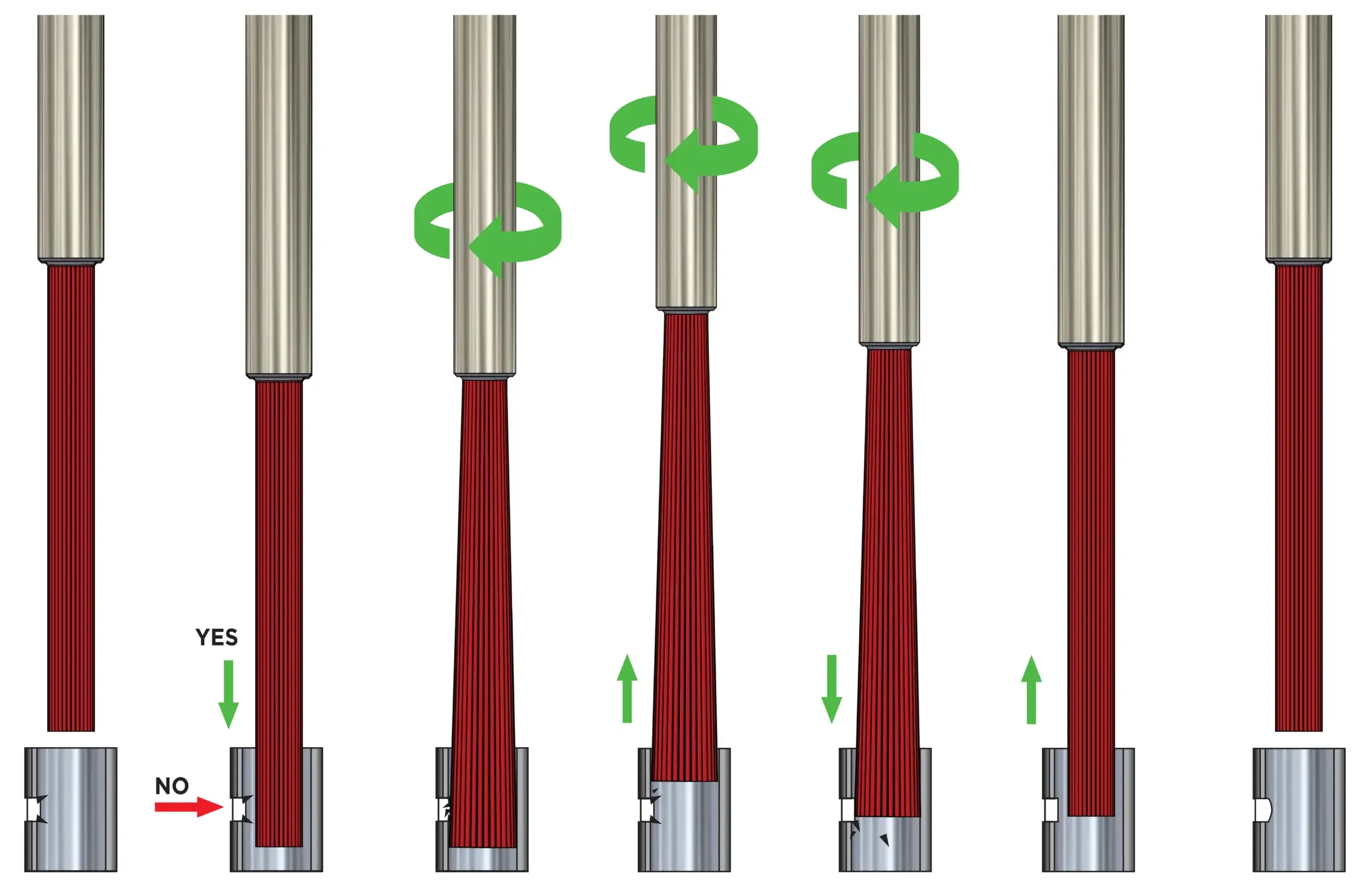
Important: Stroke must always extend completely past the cross-hole intersection. Adjust the number of passes — not the stroke distance.
Insert While Stationary
Insert the brush into the bore without rotation.
Start Rotation Inside the Bore
Begin rotation only after the brush is correctly positioned.
Process Through the Cross-Hole
Rotate through the cross-hole area to contact the intersecting edges.
Pull Back While Processing
Retract through the intersection to avoid pressing burrs flat.
Push Forward While Processing
Advance through the intersection to remove remaining upward-facing burrs.
Stop Rotation
Stop completely before changing direction.
Reverse Direction & Repeat
Use both CW and CCW and repeat pull-back / push-forward passes as required.
Remove While Stationary
Stop completely before withdrawing the brush.
How to Work with the UFIBER® Cross-Hole Brush — Video Demonstrations
UFIBER Cross-Hole Brush
Understanding the Relationship Between RPM and Brush Diameter:
Rotational Speed (RPM): As the speed of the brush rotation increases, the brush fibers spread outward due to centrifugal force. This results in an increase in the brush’s outer diameter.
Grit Levels: Brushes come in different grit levels, which determine their coarseness. Coarser grits (e.g., #400) tend to have less variation in diameter with increasing RPM, whereas finer grits (e.g., #1000 and above) show a more pronounced increase in diameter.
How to Use the UFIBER® Cross-Hole Brush
- Insert the brush without rotation: Keep the brush stationary during insertion to avoid bristle damage or scattering.
- Rotate through the cross-hole: Use both clockwise and counterclockwise rotation for consistent edge quality.
- Pull the brush back while processing: This prevents burrs from being pressed against the inner surface.
- Push the brush forward while processing: This helps remove any remaining upward-facing burrs.
- Stop the brush rotation.
- Change rotation direction.
- Repeat steps 3–6 as needed.
- Remove the brush while stationary: Make sure the brush has completely stopped before removal.
Cross-Hole operating sequence: Insert stationary, start rotation only inside the bore, process in both directions as required, stop before reversing, and remove only after rotation has completely stopped.
Cross-Hole Brush Diameter Control
RPM Increases Working Diameter
As RPM increases, centrifugal force spreads the ceramic fibers outward.
Coarser Grits
Coarser grits generally require higher RPM for equivalent expansion.
Finer Grits
Finer grits can show more diameter change as RPM changes.
RPM selection: Use pilot-hole diameter + selected brush size + grit. Conventional DOC is not applicable.
Using the Cross-Hole Brush with Different Hole Geometries
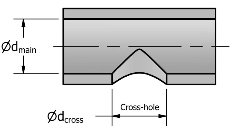
T-Shaped Hole
dcross < dmain
The cross-hole diameter must be smaller than the main-bore diameter.
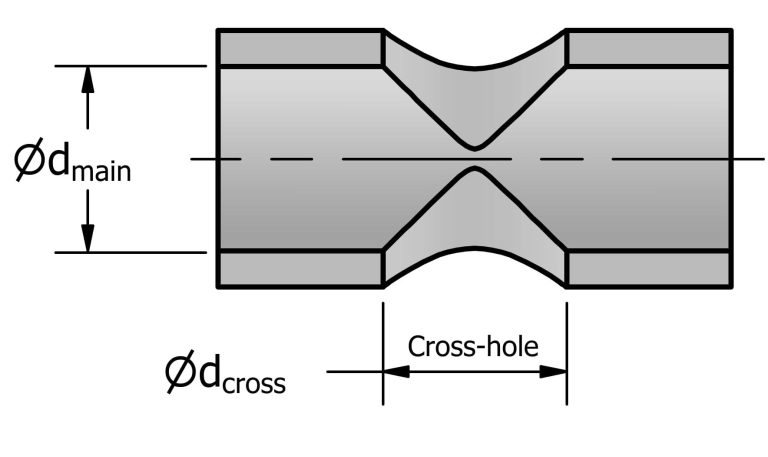
Cross-Shaped Hole
dcross ≤ 0.7 × dmain
The cross-hole diameter should be 70% or less of the main bore.
UFIBER® Cross-Hole Brush — Machining Recommendations
Machining Recommendations
Complete material-by-material starting parameters for cross-hole deburring and polishing. Use the ISO filters or search box to find a material or grade, then use the grit guide below together with the RPM calculator.
| WORKPIECE MATERIAL | DEBURRING | POLISHING | COOLANT Recommended Method |
||||||||||
|---|---|---|---|---|---|---|---|---|---|---|---|---|---|
| ISO | Material Group | Material Details | Condition | AISI / SAE / ASTM DIN W.-Nr. |
RPM Pilot hole + grit |
Feed mm/min | in/min |
Stroke / Passes | UFIBER Deburring Grit | RPM Pilot hole + grit |
Feed mm/min | in/min |
Stroke / Passes | UFIBER Polishing Grit | |
| P | Non-alloy steel and cast steel, free cutting steel | <0.25% C | Annealed | 1020 1.0044 | Use RPM CALCULATOR pilot hole + grit |
300–380 / 11.8–15.0 | 2–3 passes Stroke 5 mm past |
#400 / #600 #800 fine burrs |
Use RPM CALCULATOR pilot hole + grit |
350–450 / 13.8–17.7 | 3–4 passes Stroke 5 mm past |
#800 → #1200 | Air / Wet |
| P | Non-alloy steel and cast steel, free cutting steel | ≥0.25% C | Annealed | 1035 1.0501 | Use RPM CALCULATOR pilot hole + grit |
300–380 / 11.8–15.0 | 2–3 passes Stroke 5 mm past |
#400 / #600 #800 fine burrs |
Use RPM CALCULATOR pilot hole + grit |
350–450 / 13.8–17.7 | 3–4 passes Stroke 5 mm past |
#800 → #1200 | Air / Wet |
| P | Non-alloy steel and cast steel, free cutting steel | <0.55% C | Quenched and tempered | 1045 1.1201 | Use RPM CALCULATOR pilot hole + grit |
250–320 / 9.8–12.6 | 2–4 passes Stroke 5 mm past |
#150 / #200 / #400 | Use RPM CALCULATOR pilot hole + grit |
300–380 / 11.8–15.0 | 3–5 passes Stroke 5 mm past |
#400 → #800 #1000 / #1200 final |
Wet preferred |
| P | Non-alloy steel and cast steel, free cutting steel | ≥0.55% C | Annealed | 1055 1.0535 | Use RPM CALCULATOR pilot hole + grit |
300–380 / 11.8–15.0 | 2–3 passes Stroke 5 mm past |
#150 / #200 / #400 | Use RPM CALCULATOR pilot hole + grit |
350–450 / 13.8–17.7 | 3–4 passes Stroke 5 mm past |
#400 → #800 #1000 / #1200 final |
Air / Wet |
| P | Non-alloy steel and cast steel, free cutting steel | ≥0.55% C | Quenched and tempered | 1060 1.1221 | Use RPM CALCULATOR pilot hole + grit |
250–320 / 9.8–12.6 | 2–4 passes Stroke 5 mm past |
#150 / #200 / #400 | Use RPM CALCULATOR pilot hole + grit |
300–380 / 11.8–15.0 | 3–5 passes Stroke 5 mm past |
#400 → #800 #1000 / #1200 final |
Wet preferred |
| P | Low alloy and cast steel (<5% alloying elements) | — | Annealed | G92600 1.5028 | Use RPM CALCULATOR pilot hole + grit |
300–380 / 11.8–15.0 | 2–3 passes Stroke 5 mm past |
#400 / #600 #800 fine burrs |
Use RPM CALCULATOR pilot hole + grit |
350–450 / 13.8–17.7 | 3–4 passes Stroke 5 mm past |
#800 → #1200 | Air / Wet |
| P | Low alloy and cast steel (<5% alloying elements) | — | Quenched and tempered | 4130 1.7218 | Use RPM CALCULATOR pilot hole + grit |
250–320 / 9.8–12.6 | 2–4 passes Stroke 5 mm past |
#150 / #200 / #400 | Use RPM CALCULATOR pilot hole + grit |
300–380 / 11.8–15.0 | 3–5 passes Stroke 5 mm past |
#400 → #800 #1000 / #1200 final |
Wet preferred |
| P | Low alloy and cast steel (<5% alloying elements) | — | Quenched and tempered | 4142 1.2332 | Use RPM CALCULATOR pilot hole + grit |
300–380 / 11.8–15.0 | 2–3 passes Stroke 5 mm past |
#150 / #200 / #400 | Use RPM CALCULATOR pilot hole + grit |
350–450 / 13.8–17.7 | 3–4 passes Stroke 5 mm past |
#400 → #800 #1000 / #1200 final |
Air / Wet |
| P | Low alloy and cast steel (<5% alloying elements) | — | Quenched and tempered | 5045 1.7006 | Use RPM CALCULATOR pilot hole + grit |
300–380 / 11.8–15.0 | 2–3 passes Stroke 5 mm past |
#150 / #200 / #400 | Use RPM CALCULATOR pilot hole + grit |
350–450 / 13.8–17.7 | 3–4 passes Stroke 5 mm past |
#400 → #800 #1000 / #1200 final |
Air / Wet |
| P | High alloyed steel, cast steel and tool steel | — | Annealed | H13 1.2344 | Use RPM CALCULATOR pilot hole + grit |
250–320 / 9.8–12.6 | 2–4 passes Stroke 5 mm past |
#150 / #200 / #400 | Use RPM CALCULATOR pilot hole + grit |
300–380 / 11.8–15.0 | 3–5 passes Stroke 5 mm past |
#400 → #800 #1000 / #1200 final |
Wet preferred |
| P | High alloyed steel, cast steel and tool steel | — | Quenched and tempered | M33 1.3249 | Use RPM CALCULATOR pilot hole + grit |
250–320 / 9.8–12.6 | 2–4 passes Stroke 5 mm past |
#150 / #200 / #400 | Use RPM CALCULATOR pilot hole + grit |
300–380 / 11.8–15.0 | 3–5 passes Stroke 5 mm past |
#400 → #800 #1000 / #1200 final |
Wet preferred |
| P | Stainless steel and cast steel | Ferritic / martensitic | — | 420 1.4021 | Use RPM CALCULATOR pilot hole + grit |
250–320 / 9.8–12.6 | 2–4 passes Stroke 5 mm past |
#150 / #200 / #400 | Use RPM CALCULATOR pilot hole + grit |
300–380 / 11.8–15.0 | 3–5 passes Stroke 5 mm past |
#400 → #800 #1000 / #1200 final |
Wet preferred |
| P | Stainless steel and cast steel | Martensitic | — | — — | Use RPM CALCULATOR pilot hole + grit |
250–320 / 9.8–12.6 | 2–4 passes Stroke 5 mm past |
#150 / #200 / #400 | Use RPM CALCULATOR pilot hole + grit |
300–380 / 11.8–15.0 | 3–5 passes Stroke 5 mm past |
#400 → #800 #1000 / #1200 final |
Wet preferred |
| M | Stainless steel | Austenitic, duplex | — | 304L 1.4306 | Use RPM CALCULATOR pilot hole + grit |
250–350 / 9.8–13.8 | 2–3 passes Stroke 5 mm past |
#400 / #600 #800 fine burrs |
Use RPM CALCULATOR pilot hole + grit |
300–400 / 11.8–15.7 | 3–4 passes Stroke 5 mm past |
#800 → #1200 | Wet recommended |
| K | Gray cast iron (GG) | Ferritic / pearlitic | — | Class 25 0.6015 | Use RPM CALCULATOR pilot hole + grit |
250–350 / 9.8–13.8 | 2–4 passes Stroke 5 mm past |
#200 / #400 #600 fine burrs |
Use RPM CALCULATOR pilot hole + grit |
300–400 / 11.8–15.7 | 3–5 passes Stroke 5 mm past |
#600 → #1000 | Air preferred |
| K | Gray cast iron (GG) | Pearlitic / martensitic | — | Grade H20 36037 | Use RPM CALCULATOR pilot hole + grit |
250–350 / 9.8–13.8 | 2–4 passes Stroke 5 mm past |
#150 / #200 / #400 | Use RPM CALCULATOR pilot hole + grit |
300–400 / 11.8–15.7 | 3–5 passes Stroke 5 mm past |
#400 → #800 #1000 / #1200 final |
Air preferred |
| K | Nodular cast iron (GGG) | Ferritic | — | 60-40-18 0.7043 | Use RPM CALCULATOR pilot hole + grit |
300–400 / 11.8–15.7 | 2–3 passes Stroke 5 mm past |
#400 / #600 | Use RPM CALCULATOR pilot hole + grit |
350–450 / 13.8–17.7 | 3–4 passes Stroke 5 mm past |
#800 → #1200 | Air preferred |
| K | Nodular cast iron (GGG) | Pearlitic | — | F33500 0.705 | Use RPM CALCULATOR pilot hole + grit |
250–350 / 9.8–13.8 | 2–4 passes Stroke 5 mm past |
#150 / #200 / #400 | Use RPM CALCULATOR pilot hole + grit |
300–400 / 11.8–15.7 | 3–5 passes Stroke 5 mm past |
#400 → #800 #1000 / #1200 final |
Air preferred |
| K | Malleable cast iron | Ferritic | — | A47 0.8135 | Use RPM CALCULATOR pilot hole + grit |
300–400 / 11.8–15.7 | 2–3 passes Stroke 5 mm past |
#400 / #600 | Use RPM CALCULATOR pilot hole + grit |
350–450 / 13.8–17.7 | 3–4 passes Stroke 5 mm past |
#800 → #1200 | Air preferred |
| K | Malleable cast iron | Pearlitic | — | A220 Class 0.8155 | Use RPM CALCULATOR pilot hole + grit |
250–350 / 9.8–13.8 | 2–4 passes Stroke 5 mm past |
#150 / #200 / #400 | Use RPM CALCULATOR pilot hole + grit |
300–400 / 11.8–15.7 | 3–5 passes Stroke 5 mm past |
#400 → #800 #1000 / #1200 final |
Air preferred |
| N | Aluminum-wrought alloys | — | Not hardenable | 5005 3.3315 | Use RPM CALCULATOR pilot hole + grit |
350–500 / 13.8–19.7 | 2 passes Stroke 5 mm past |
#800 / #1200 | Use RPM CALCULATOR pilot hole + grit |
400–550 / 15.7–21.7 | 3–4 passes Stroke 5 mm past |
#1200 → #2000 | Wet / MQL |
| N | Aluminum-wrought alloys | — | Hardenable | 7075 3.4365 | Use RPM CALCULATOR pilot hole + grit |
350–500 / 13.8–19.7 | 2 passes Stroke 5 mm past |
#800 / #1200 | Use RPM CALCULATOR pilot hole + grit |
400–550 / 15.7–21.7 | 3–4 passes Stroke 5 mm past |
#1200 → #2000 | Wet / MQL |
| N | Aluminum-cast alloys | ≤12% Si | Not hardenable | 518 3.3292 | Use RPM CALCULATOR pilot hole + grit |
350–500 / 13.8–19.7 | 2 passes Stroke 5 mm past |
#800 / #1200 | Use RPM CALCULATOR pilot hole + grit |
400–550 / 15.7–21.7 | 3–4 passes Stroke 5 mm past |
#1200 → #2000 | Wet / MQL |
| N | Aluminum-cast alloys | ≤12% Si | Hardenable | 515 3.3241 | Use RPM CALCULATOR pilot hole + grit |
350–500 / 13.8–19.7 | 2 passes Stroke 5 mm past |
#800 / #1200 | Use RPM CALCULATOR pilot hole + grit |
400–550 / 15.7–21.7 | 3–4 passes Stroke 5 mm past |
#1200 → #2000 | Wet / MQL |
| N | Aluminum-cast alloys | >12% Si | High temperature | 390 — | Use RPM CALCULATOR pilot hole + grit |
350–500 / 13.8–19.7 | 2 passes Stroke 5 mm past |
#600 / #800 | Use RPM CALCULATOR pilot hole + grit |
400–550 / 15.7–21.7 | 3–4 passes Stroke 5 mm past |
#1000 → #1200 | Wet / MQL |
| N | Copper alloys | >1% Pb | Free cutting | C36000 2.0375 | Use RPM CALCULATOR pilot hole + grit |
300–450 / 11.8–17.7 | 2 passes Stroke 5 mm past |
#800 / #1200 | Use RPM CALCULATOR pilot hole + grit |
350–500 / 13.8–19.7 | 3–4 passes Stroke 5 mm past |
#1200 → #2000 | Air / Wet |
| N | Copper alloys | — | Brass | C22000 2.023 | Use RPM CALCULATOR pilot hole + grit |
300–450 / 11.8–17.7 | 2 passes Stroke 5 mm past |
#800 / #1200 | Use RPM CALCULATOR pilot hole + grit |
350–500 / 13.8–19.7 | 3–4 passes Stroke 5 mm past |
#1200 → #2000 | Air / Wet |
| N | Copper alloys | — | Electrolytic copper | C63000 2.0966 | Use RPM CALCULATOR pilot hole + grit |
300–450 / 11.8–17.7 | 2 passes Stroke 5 mm past |
#800 / #1200 | Use RPM CALCULATOR pilot hole + grit |
350–500 / 13.8–19.7 | 3–4 passes Stroke 5 mm past |
#1200 → #2000 | Air / Wet |
| N | Non-metallic | Duroplastics, fiber plastics | — | Bakelite — | Use RPM CALCULATOR pilot hole + grit |
250–350 / 9.8–13.8 | 2 passes Stroke 5 mm past |
#2000 / #3000 | Use RPM CALCULATOR pilot hole + grit |
300–400 / 11.8–15.7 | 3–4 passes Stroke 5 mm past |
#3000 → #6000 | Dry air + extraction |
| N | Non-metallic | Hard rubber | — | Ebonite — | Use RPM CALCULATOR pilot hole + grit |
250–350 / 9.8–13.8 | 2 passes Stroke 5 mm past |
#2000 / #3000 | Use RPM CALCULATOR pilot hole + grit |
300–400 / 11.8–15.7 | 3–4 passes Stroke 5 mm past |
#3000 → #6000 | Dry air + extraction |
| S | High temperature alloys | Fe based | Annealed | 330 1.4864 | Use RPM CALCULATOR pilot hole + grit |
200–300 / 7.9–11.8 | 2–4 passes Stroke 5 mm past |
#150 / #200 / #400 | Use RPM CALCULATOR pilot hole + grit |
250–350 / 9.8–13.8 | 3–5 passes Stroke 5 mm past |
#400 → #800 #1000 / #1200 final |
Wet recommended |
| S | High temperature alloys | Fe based | Hardened | S590 1.4977 | Use RPM CALCULATOR pilot hole + grit |
200–300 / 7.9–11.8 | 2–4 passes Stroke 5 mm past |
#150 / #200 / #400 | Use RPM CALCULATOR pilot hole + grit |
250–350 / 9.8–13.8 | 3–5 passes Stroke 5 mm past |
#400 → #800 #1000 / #1200 final |
Wet recommended |
| S | High temperature alloys | Ni or Co based | Annealed | Incoloy 825 2.4858 | Use RPM CALCULATOR pilot hole + grit |
200–300 / 7.9–11.8 | 2–4 passes Stroke 5 mm past |
#150 / #200 / #400 | Use RPM CALCULATOR pilot hole + grit |
250–350 / 9.8–13.8 | 3–5 passes Stroke 5 mm past |
#400 → #800 #1000 / #1200 final |
Wet recommended |
| S | High temperature alloys | Ni or Co based | Hardened | Inconel 718 2.4668 | Use RPM CALCULATOR pilot hole + grit |
200–300 / 7.9–11.8 | 2–4 passes Stroke 5 mm past |
#150 / #200 / #400 | Use RPM CALCULATOR pilot hole + grit |
250–350 / 9.8–13.8 | 3–5 passes Stroke 5 mm past |
#400 → #800 #1000 / #1200 final |
Wet recommended |
| S | High temperature alloys | Ni or Co based | Cast | Nimocast K24 2.4674 | Use RPM CALCULATOR pilot hole + grit |
200–300 / 7.9–11.8 | 2–4 passes Stroke 5 mm past |
#150 / #200 / #400 | Use RPM CALCULATOR pilot hole + grit |
250–350 / 9.8–13.8 | 3–5 passes Stroke 5 mm past |
#400 → #800 #1000 / #1200 final |
Wet recommended |
| S | Titanium alloys | — | Pure | Titanium G.1 3.7024 | Use RPM CALCULATOR pilot hole + grit |
200–300 / 7.9–11.8 | 2–4 passes Stroke 5 mm past |
#150 / #200 / #400 | Use RPM CALCULATOR pilot hole + grit |
250–350 / 9.8–13.8 | 3–5 passes Stroke 5 mm past |
#400 → #800 #1000 / #1200 final |
Wet recommended |
| S | Titanium alloys | — | Alpha+beta alloys, hardened | Titanium G.5 3.7165 | Use RPM CALCULATOR pilot hole + grit |
200–300 / 7.9–11.8 | 2–4 passes Stroke 5 mm past |
#150 / #200 / #400 | Use RPM CALCULATOR pilot hole + grit |
250–350 / 9.8–13.8 | 3–5 passes Stroke 5 mm past |
#400 → #800 #1000 / #1200 final |
Wet recommended |
| H | Hardened steel | — | Hardened | HARDOX 500 — | Use RPM CALCULATOR pilot hole + grit |
300 / 11.8 | 2 passes minimum Stroke 5 mm past |
#150 / #200 / #400 | Use RPM CALCULATOR pilot hole + grit |
300 / 11.8 | 3–4 passes Stroke 5 mm past |
#400 → #800 #1000 / #1200 final |
Wet preferred |
| H | Hardened steel | — | Hardened | HARDOX Extreme — | Use RPM CALCULATOR pilot hole + grit |
300 / 11.8 | 2 passes minimum Stroke 5 mm past |
#150 / #200 / #400 | Use RPM CALCULATOR pilot hole + grit |
300 / 11.8 | 3–4 passes Stroke 5 mm past |
#400 → #800 #1000 / #1200 final |
Wet preferred |
| H | Chilled cast iron | — | Cast | A532 IIIA 25% Cr 0.965 | Use RPM CALCULATOR pilot hole + grit |
300 / 11.8 | 2 passes minimum Stroke 5 mm past |
#150 / #200 / #400 | Use RPM CALCULATOR pilot hole + grit |
300 / 11.8 | 3–4 passes Stroke 5 mm past |
#400 → #800 #1000 / #1200 final |
Wet preferred |
| H | Hardened cast iron | — | Hardened | A532 IID 20% CrMo 0.9645 | Use RPM CALCULATOR pilot hole + grit |
300 / 11.8 | 2 passes minimum Stroke 5 mm past |
#150 / #200 / #400 | Use RPM CALCULATOR pilot hole + grit |
300 / 11.8 | 3–4 passes Stroke 5 mm past |
#400 → #800 #1000 / #1200 final |
Wet preferred |
Grit Selection Guide
Choose grit according to burr strength, edge-control requirement and desired finish. For cross-hole work, always combine grit selection with the RPM calculator based on pilot-hole diameter and grit.
Hard / abrasive materials
Heat-treated steels / difficult alloys
Better edge control
Balanced cutting action
Transition to finishing
Controlled surface improvement
Non-ferrous applications
Low cutting aggression
High-finish applications
Plastics / composites
| Application Condition | Primary Recommendation | Alternative / Progression | Cross-Hole Guidance |
|---|---|---|---|
| Heavy resistant burr / hard abrasive material | #150 (G) | #200 (P) → #400 (V) | Use the coarsest grit only when the burr and edge condition require it. Select RPM by pilot-hole diameter + grit and verify brush expansion. |
| General hard-material deburring | #200 (P) | #400 (V) for smaller burrs | Suitable as the general starting family for heat-treated steels and difficult alloys when #150 is unnecessarily aggressive. |
| General steel / stainless / cast iron | #400 (V) / #600 (O) | #800 (B) for fine burrs | Use #400 for stronger cutting action, #600 for balanced deburring, and #800 where edge rounding must be minimized. |
| Fine burr / precision edge | #800 (B) | #1000 (W) | Use finer grit when the burr is small and the main objective is controlled edge conditioning or improved internal finish. |
| Polishing / finishing metals | #1000 (W) / #1200 (R) | #2000 (M) where a finer finish is needed | Use after burr removal when the objective shifts from cutting power to surface finish. |
| Non-metallic / very fine finishing | #2000 (M) / #3000 (Z) | #6000 (A) final | Use for plastics, hard rubber, composites and micro-finish applications with dry-air extraction where appropriate. |
Controlling Cross-Hole Deburring & Finishing Performance
Controlling
Cross-Hole
Deburring
and
Finishing
Performance
| Operation Type | Grit Selection | Feed | RPM | Passes | Effect / Purpose |
|---|---|---|---|---|---|
|
1
Deburring
Power Up |
Coarser grit | ↓ | ↑ | ↑ | More aggressive burr removal, but increased brush wear and greater risk of edge rounding. |
|
2
Deburring
Power Down / Tool Life Up |
Finer grit | ↑ | ↓ | ↓ | Softer contact, reduced material removal, lower brush wear and longer tool life. |
|
3
Finishing
Quality Up |
Finer grit | ↓ | ↔ | ↑ | Improved internal finish and tool-mark reduction with controlled material removal. |
|
4
Gentle Finishing /
Stock Removal Down |
Finest suitable grit |
↑ | ↓ | ↓ | Minimal stock removal and reduced risk of excessive edge rounding. |
Adjust the number of passes — not the stroke distance. Start with two directional passes and optimize gradually.
Important: Keep the stroke long enough to pass completely through the intersection. Tune the process with passes, feed, grit and RPM.
UFIBER® Cross-Hole Brush — RPM Calculator
Cross-Hole Brush Safety Precautions & Instructions
Tool & Machine Safety
Stay within the recommended and absolute maximum RPM.
Use the brush inside the cylinder/workpiece area.
Use centered, properly aligned bores and cross holes.
Grip the shank by at least 30 mm.
Use a matching chuck and controlled-RPM equipment.
Stop immediately if vibration or abnormal behavior occurs.
Operator & Work Area Safety
Wear appropriate eye, respiratory, hand and hearing protection.
Use barriers and suitable dust/particle collection.
Keep floors clear of oil, water, chips and debris.
Do not use near flammable liquids or explosive atmospheres.
Avoid prolonged fixed-point machining and hot-surface contact.
CAUTION: Rotating brushes, fragments, burrs and machining debris can cause serious injury. Validate the process before production use.
UFIBER® Cross-Hole Brush — 3D Models
Cross-Hole Brush STEP Models
For machine simulation, programming and tooling preparation.