

UBACK®Back-Machining System
Machine hidden rear features without flipping the workpiece. Coolant-actuated UX tool-holders carry USPOT and UCHAMF inserts for automated CNC back spotfacing, counterboring, chamfering and countersinking.
UBACK at a glance
Screening values. The configurator confirms the exact holder and insert.
- Application
- Hidden rear featuresNo workpiece flipping
- Pilot-hole range
- Ø8–25 mm / 0.315–0.984″
- Actuation
- HydraulicInternal coolant, emulsion or air
- Minimum pressure
- 6 bar / 90 PSI
- Insert families
- USPOT + UCHAMFSpotface, counterbore, chamfer, countersink
- Tool-holders
- UBACK UX / DURASHIELDCorrosion-resistant platform
Compatibility: the insert series must match the UX holder series, and the axial reach must stay within the holder RFC limit.
One UBACK platform. Two rear-machining insert families.
Start from the feature you need to produce. The insert series must match the selected UX tool-holder series.
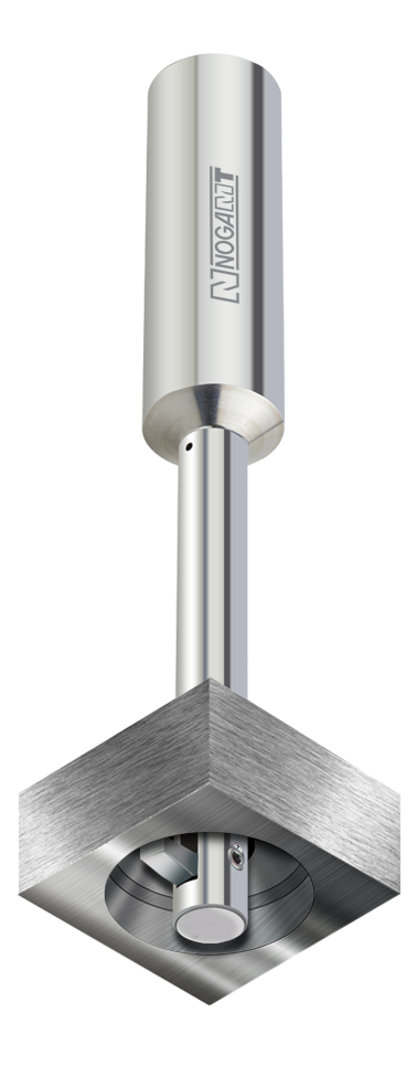
Back spotfacing & counterboring
Produce a flat-bottom rear spotface or counterbore through an existing pilot hole. USPOT is semi-standard: configured to the diameter, corner radius, chip-former and coating your application needs.
- Flat-bottom back spotface or counterbore
- Target ØD tolerance ±0.1 mm / ±0.004″
- Continuous and interrupted cuts
- Standard UX/USPOT envelope up to Ø57.5 mm
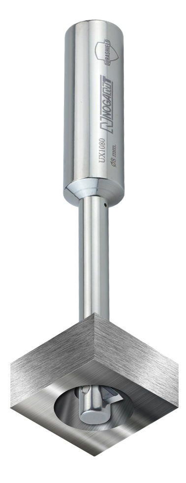
Back chamfering & countersinking
Machine hidden rear chamfers and countersinks with standard 82° or 90° UCHAMF inserts. Special angles are available for customer-specific applications.
- Rear countersinking and controlled back chamfering
- 82° and 90° standard insert families
- Special angles on request
- Same coolant-actuated UX tool-holder platform
Designed to remove extra setups from rear-feature machining.
The UX hydraulic mechanism turns internal coolant pressure into repeatable insert movement, so hidden features are machined from the accessible side of the part.
Series B–G cover pilot holes from Ø8 to Ø25 mm.
Choose the UX series from the pilot-hole diameter first, then check the feature diameter and axial reach against the holder and insert family.
| Series | Pilot-hole range Ød | USPOT max ØD | UCHAMF 82° max ØD | UCHAMF 90° max ØD | UX holder shank |
|---|---|---|---|---|---|
| B | 8–10 mm / 0.315–0.394″ | 23 mm / 0.906″ | 17 mm / 0.669″ | 18 mm / 0.709″ | Ø16 mm |
| C | 11–13 mm / 0.433–0.512″ | 30 mm / 1.181″ | 24 mm / 0.945″ | 25 mm / 0.984″ | Ø16 mm |
| D | 14–16 mm / 0.551–0.630″ | 37 mm / 1.457″ | 29 mm / 1.142″ | 31 mm / 1.220″ | Ø20 mm |
| E | 17–19 mm / 0.669–0.748″ | 44 mm / 1.732″ | 34 mm / 1.339″ | 37 mm / 1.457″ | Ø20 mm |
| F | 20–22 mm / 0.787–0.866″ | 50.5 mm / 1.988″ | 39 mm / 1.535″ | 42 mm / 1.654″ | Ø25 mm |
| G | 23–25 mm / 0.906–0.984″ | 57.5 mm / 2.264″ | 44 mm / 1.732″ | 47 mm / 1.850″ | Ø25 mm |
USPOT ØD is set per application. UCHAMF 82° / 90° values are the largest standard diameters at the upper pilot size of each series.
Hydraulic insert control using the machine’s existing coolant system.
The UX holder turns pressure through the spindle into controlled insert movement, so back-machining runs as an automated CNC cycle.
Pressure controls the cutting position.
- Closed during entryThe insert stays inside the holder envelope while it passes through the pilot hole.
- Coolant actuates the mechanismMinimum operating pressure: 6 bar / 90 PSI.
- Cut on the hidden sideUSPOT or UCHAMF machines the programmed rear feature.
- Close before returnThe insert retracts before the tool comes back through the pilot hole.
Built for more than a simple flat rear face.
UBACK handles continuous and interrupted rear features. For interrupted cuts, use the cooling and cutting-data reductions in the Technical Center.
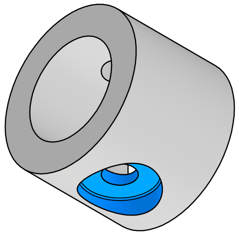
Cylindrical bore
Rear counterbore or spotface on a cylindrical geometry.
Internal coolant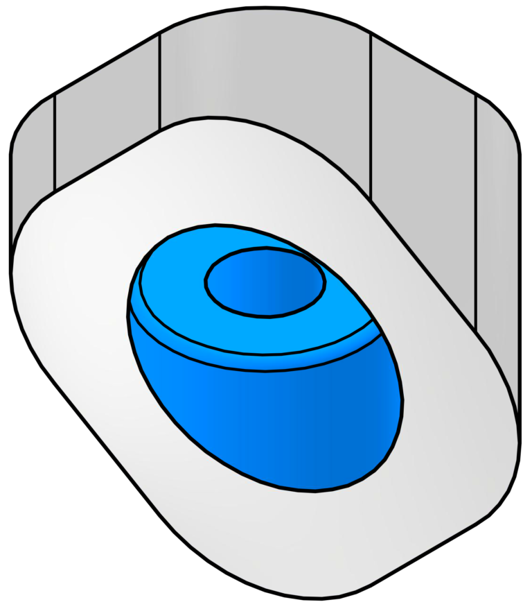
Sloped surface
Rear spotface or counterbore where the back surface is inclined.
External coolant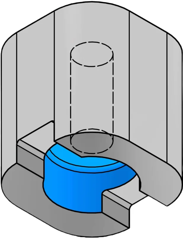
Slot / interrupted cut
Fully interrupted rear machining across an open slot or broken surface.
External coolant · reduce cutting data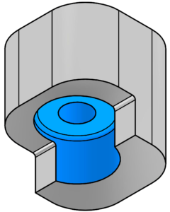
Shoulder type A
Fully interrupted shoulder geometry with reduced cutting stability.
External coolant · reduce cutting data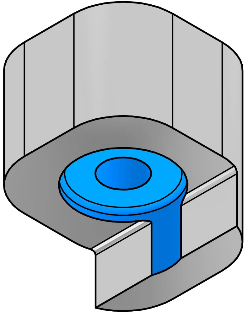
Shoulder type B
Alternative fully interrupted shoulder with repeated entry and exit.
External coolant · reduce cutting dataProgramming, cutting data, cooling and insert technology.
The Technical Center covers USPOT and UCHAMF programming, continuous and interrupted cuts, insert replacement, cooling setup, coatings, chip-formers and cutting data by material.

Built for strength, corrosion resistance and repeatable CNC use.
UBACK UX holders belong to the NOGA MT DURASHIELD platform: corrosion-resistant, passivated material that keeps its structural integrity and repeatable insert movement in demanding production.
- StrengthHandles demanding cutting loads.
- ToughnessReliable over repeated production cycles.
- Wear resistanceLong-term holder durability.
- Heat resistanceStable in machining environments.
- Corrosion resistancePassivated protection for harsh conditions.
- PrecisionConsistent hydraulic insert deployment.
Common UBACK selection questions
What is the difference between USPOT and UCHAMF?
What pressure is required to operate UBACK?
What pilot-hole diameters are covered?
Can UBACK machine interrupted cuts?
Can one UX holder use both USPOT and UCHAMF?
Are the holder and insert sold together?
How do I select the correct UBACK tool?
Can NOGA MT support a special application?
Send the application drawing and let NOGA MT check the complete setup.
Include the pilot-hole diameter, rear-feature geometry, axial reach, workpiece material and available coolant pressure. We’ll help match the UX holder, insert family and starting cutting data.