
UFIBER® Floating Dampers Controlled Contact Compensation for CNC & Robotic Finishing
Spring-loaded floating holders engineered to maintain stable UFIBER brush contact as the workpiece surface varies or the brush wears. Available in BT30 / BT40 and End-Type configurations for repeatable automated deburring, polishing and surface finishing.
Controlled Floating Compensation for UFIBER Brushes
The NOGA MT Floating Damper is engineered for reliable deburring and surface finishing, compensating for surface irregularities and brush wear to maintain stable tool contact and consistent results. Its integrated spring mechanism delivers controlled, constant pressure, ensuring uniform performance in CNC and automated applications.
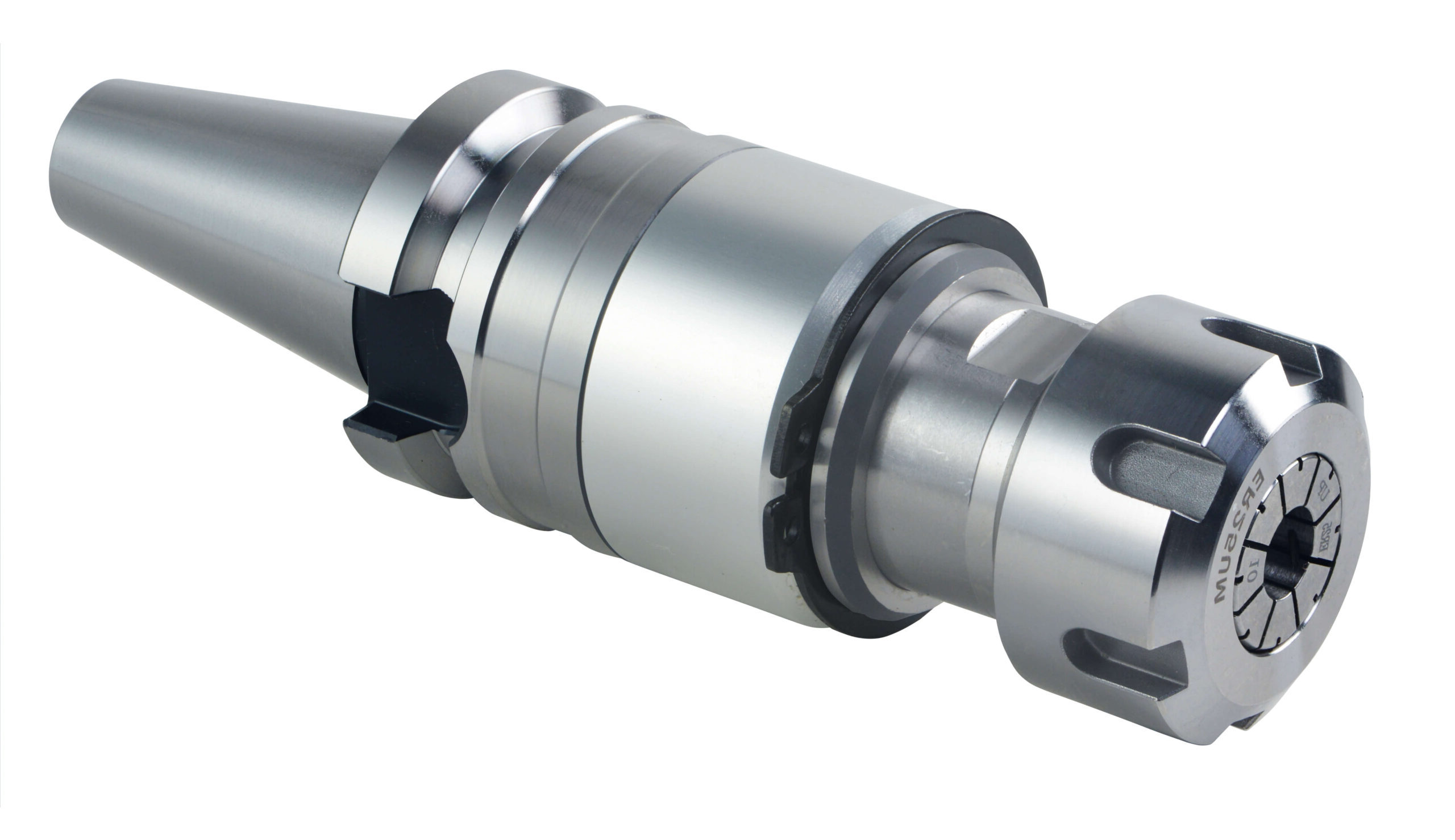
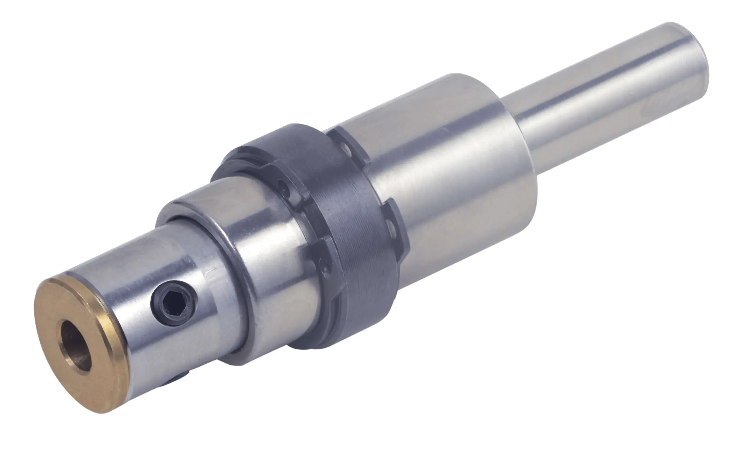
Key Advantages
The floating mechanism keeps brush engagement more stable as the process, workpiece surface and brush condition change.
Maintains uniform cutting conditions throughout the process.
Minimizes the need for precise depth adjustments.
Improves consistency of edge finishing.
Reduces tool wear and extends service life.
Eliminates programming adjustments to compensate for bristle wear.
Applications & Automation
Designed for finishing processes where consistent brush contact is important across CNC and robotic applications.
- Surface finishing using UFIBER brushes
- Automated deburring and polishing on CNC machines
- Robotic deburring and polishing systems
- Repeatable finishing where stable brush contact is required
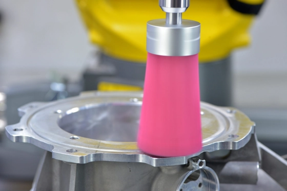
Product Series
Available floating dampers for BT30 / BT40 machine interfaces and compact End-Type applications.
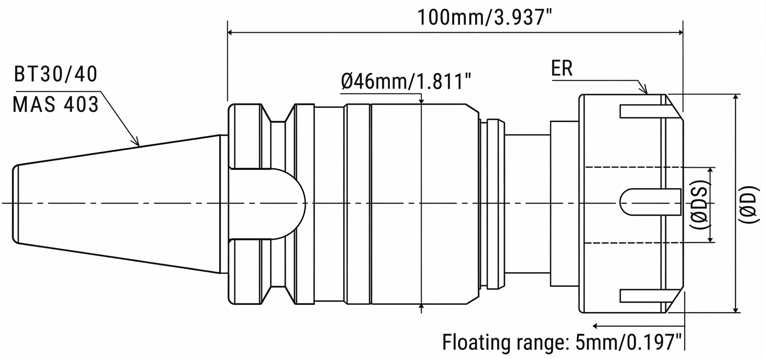
| SKU | Description | ØDS |
|---|---|---|
| UF8853 | UF-FD-DS06-BT30 | 6 mm / 0.236″ |
| UF8854 | UF-FD-DS10-BT30 | 10 mm / 0.394″ |
| UF8855 | UF-FD-DS12-BT30 | 12 mm / 0.472″ |
| UF8856 | UF-FD-DS16-BT30 | 16 mm / 0.630″ |
| UF8857 | UF-FD-DS06-BT40 | 6 mm / 0.236″ |
| UF8858 | UF-FD-DS10-BT40 | 10 mm / 0.394″ |
| UF8859 | UF-FD-DS12-BT40 | 12 mm / 0.472″ |
| UF8860 | UF-FD-DS16-BT40 | 16 mm / 0.630″ |
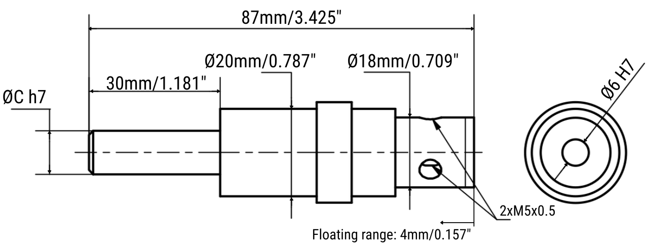
| SKU | Description | ØC | ØDS |
|---|---|---|---|
| UF8851 | UF-FD-DS06-C06 | Ø6 mm / 0.236″ | Ø6 mm / 0.236″ |
| UF8852 | UF-FD-DS10-C10 | Ø10 mm / 0.394″ | Ø10 mm / 0.394″ |
Technical Specifications
Operating limits and mechanical specifications for the BT-Series and End-Type floating dampers.
BT30 / BT40 Series
MAX 6,000 RPM| Interface | MAS 403-BT30 / BT40 |
| Max Speed | 6,000 rpm |
| Tool Shank Capacity ØDS |
Ø6 / Ø10 / Ø12 / Ø16 mm
0.236″ / 0.394″ / 0.472″ / 0.630″ |
| ER Collet |
Ultra Precision, ≤5 μm runout
ER25UM for BT30 / ØD=42 mm ER32UM for BT40 / ØD=50 mm |
| Stroke | 5 mm / 0.197″ |
| Spring Pressure | Approx. 50 N |
End-Type Series
MAX 12,000 RPM| Interface | END-TYPE |
| Max Speed | 12,000 rpm |
| Balance | High-speed balanced |
| Tool Shank Capacity | Ø6 mm / 0.236″ |
| Tool Shank Diameter ØC |
UF8851: Ø6 mm / 0.236″
UF8852: Ø10 mm / 0.394″ |
| Stroke | 4.0 mm / 0.157″ |
| Spring Pressure | Approx. 20 N |
BT-Series Spare Parts
- BT30 pull stud — M12 × 1.75
- BT40 pull stud — M16 × 2
End-Type Spare Parts
- UF0022 — Socket Allen Key 4 mm
- UF0024 — Clamping Screws, 2 × M5 × 5 × 0.5
Operating Instructions
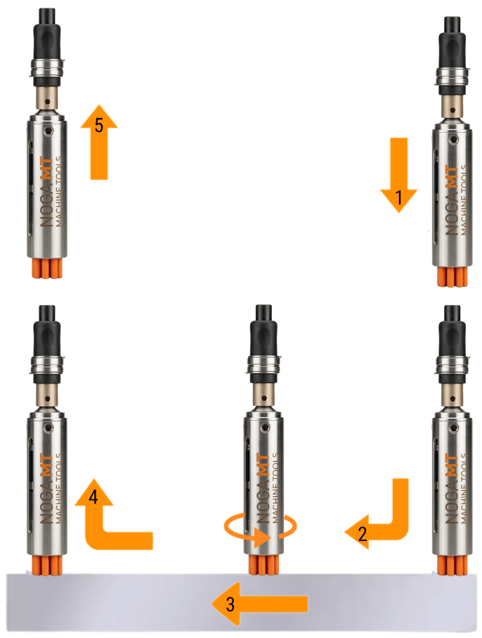
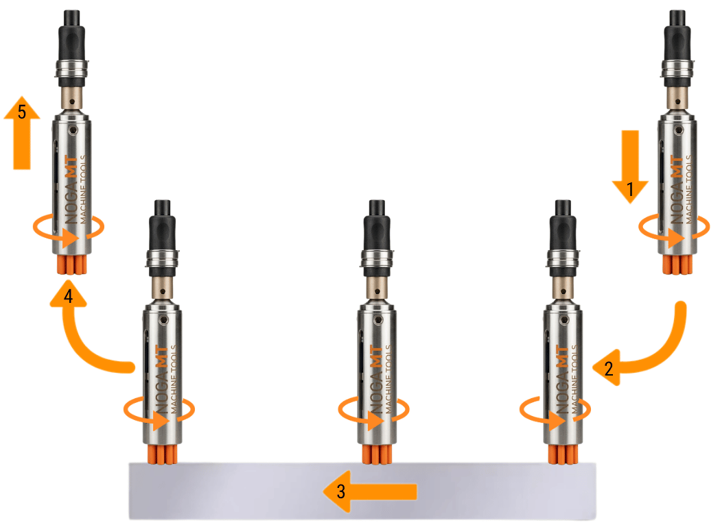
The diagrams below show the difference between Standard (Figure A) and Ramping (Figure B) entry and exit modes.
| Operation Mode | 1. Position | 2. Preload | 3. Feed | 4. Stop | 5. Retract |
|---|---|---|---|---|---|
| Standard – Figure A | Approach the tool without rotation | Compress spring and set depth | Feed with rotation | Stop rotation and feed | Retract upward vertically |
| Ramping – Figure B | Arc entry with rotation | Compress spring and set depth before feed | Feed with rotation | — | Arc exit with rotation |
Usage Guidelines
Maintain controlled axial contact and keep the floating mechanism free to move throughout the process.
Usage Guidelines
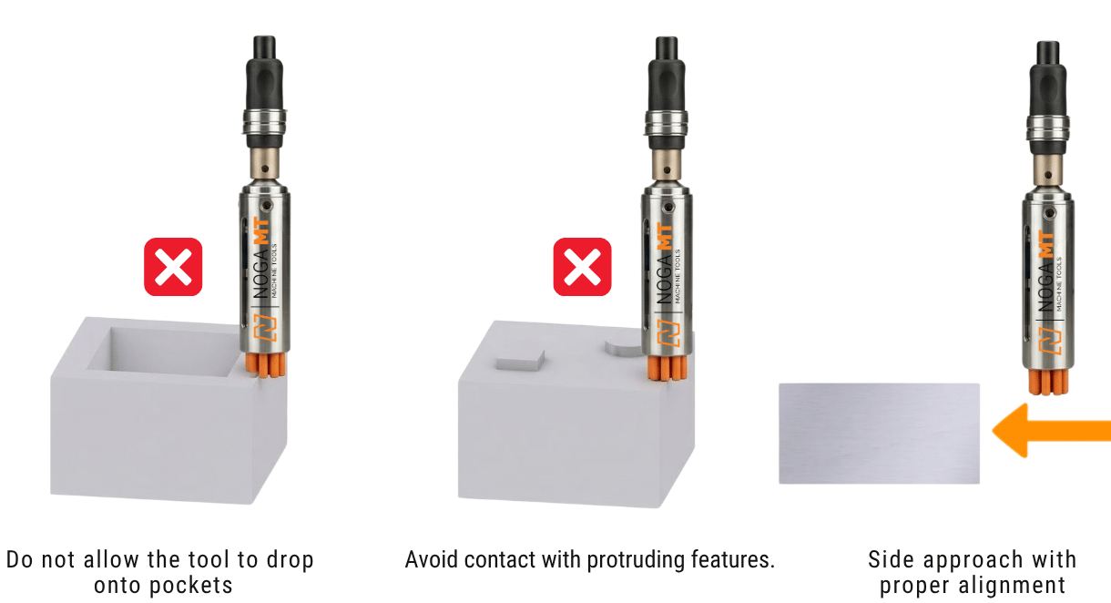
- Approach the brush vertically and engage it with the workpiece.
- Avoid side contact, as it can damage the bristles.
- Do not let the tool drop into pockets.
- Do not contact protruding features.
- Ensure the floating mechanism can move freely at all times.
- Prevent lateral side loading on the brush or tool.
Practical Recommendations
- Apply preload before starting the cutting process.
- Maintain consistent spring engagement throughout machining.
- Proper setup improves both entry and exit surface quality.
- Stable operating conditions help achieve longer tool life and repeatable results.
Precautions for Use
Verify the holder, tool and machine setup before operation and remain within the specified operating limits.
Important operating precautions
- Ensure the collet and holder are securely tightened before operation.
- Confirm that the tool shank is properly clamped in the machine chuck.
- Always wear appropriate protective equipment.
- If the tool is not fully inserted, vibration may cause loosening, detachment, breakage, or injury.
- Use a chuck that matches the shank diameter correctly.
- Operate only with equipment capable of controlling rotational speed.
- Do not use through-spindle coolant.
- After extended use, reduced spring force may affect floating function, so check functionality before use.
- During machining, particles and dust may scatter, so use suitable extraction.
- Processing dust may be harmful to health.
- Perform a short test run before use.
- Stop operation immediately if vibration or abnormal behavior occurs.
- Do not exceed maximum rotational speed, depth of cut, or brush projection.
UFIBER® Floating Dampers — Frequently Asked Questions
Quick technical answers for selection and setup.
What is the purpose of the UFIBER Floating Damper?
The UFIBER Floating Damper maintains controlled brush contact during deburring and surface finishing by compensating for workpiece variation and brush wear. It is intended for repeatable CNC and robotic finishing with UFIBER brushes.
Which collet does the BT series use?
The BT30 series uses an ER25UM ultra-precision collet and the BT40 series uses an ER32UM ultra-precision collet. The specified runout is ≤5 μm.
What tool shank sizes are supported?
The BT series supports tool shanks of Ø6, Ø10, Ø12 and Ø16 mm. The End-Type series has a Ø6 mm tool shank capacity.
Can I use through-spindle coolant?
No. Do not use through-spindle coolant. Coolant entering the holder may prevent proper floating operation.
What is the stroke?
The stroke is 5 mm (0.197″) for the BT30/BT40 series and 4.0 mm (0.157″) for the End-Type series.