
UFIBER® Technical Center
Technical information for the complete UFIBER finishing system — ceramic fiber brushes, radial ceramic fiber discs, ceramic diamond stones, Portable E-Pack, Floating Dampers and the UFIBER AI Assistant. Find product data, machining recommendations, operating guidance, safety information and application support.
Detailed UFIBER Technical Guides
Choose the UFIBER tool or system you need. The four ceramic fiber brush families remain first, followed by the Radial Ceramic Fiber Disc, Ceramic Diamond Stones, Portable E-Pack and Floating Dampers — each with a direct link to its dedicated technical page.
Surface Brush
For controlled surface deburring, edge finishing and polishing on flat or open geometries. Designed primarily for CNC, machining-center and robotic applications.
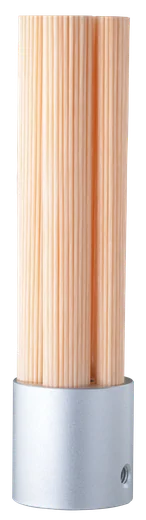
- Product range & dimensions
- Sleeves, shanks & spare parts
- Grit selection
- Machining recommendations
- RPM calculation
- Safety & 3D models
Cross-Hole Brush
For controlled deburring of internal bores and intersecting cross-holes. Fibers expand during rotation to contact internal surfaces and burr edges.

- Brush & pilot-hole selection
- Grit selection
- Insertion / withdrawal method
- Stroke & intersection geometry
- Machining recommendations
- RPM, safety & 3D models
End-Type Brush
Straight and 45° ceramic-fiber brushes for localized axial contact, chamfers, corners, recesses and difficult-to-access finishing areas.

- Straight & 45° configurations
- Product range
- Grit selection
- Machining recommendations
- Portable-use guidance
- Safety & 3D models
Point-Type Brush
Small-diameter precision brushes for bores, localized features and fine finishing where controlled access and small contact areas are required.

- Ø1.0–Ø3.0 mm product range
- Metric & inch dimensions
- Grit selection
- Machining recommendations
- Portable-use guidance
- Safety & 3D models
Radial Ceramic Fiber Disc
Thin ceramic-fiber discs for controlled radial deburring, edge finishing, local grinding and polishing in precision finishing applications.
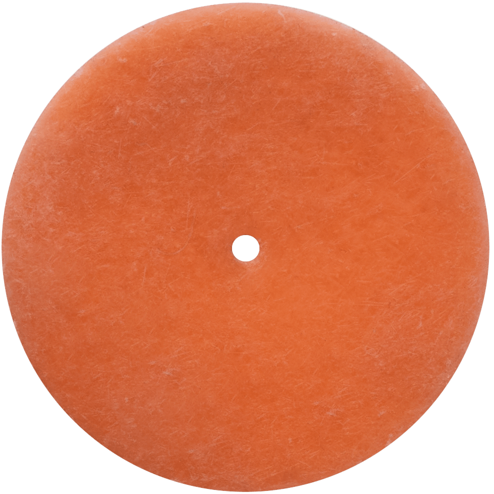
- Disc range & dimensions
- Grit selection
- Adapters & mounting
- Machining recommendations
- Maximum-speed guidance
- Safety & application information
Ceramic Diamond Stones
Point-type ceramic diamond stones for controlled precision finishing, polishing and lapping of hard and difficult-to-machine materials.
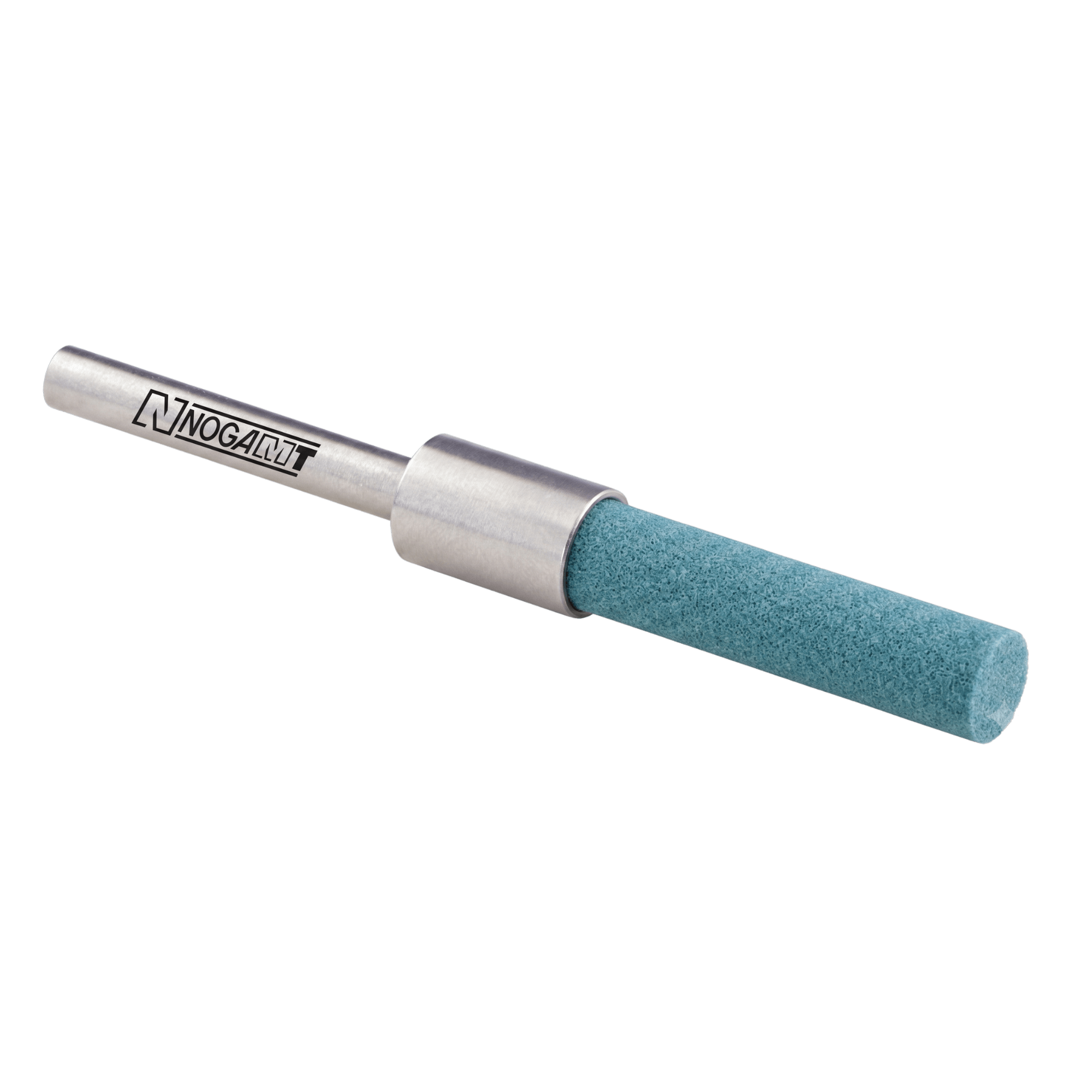
- Product range & dimensions
- Grit selection
- Speed recommendations
- Contact-force guidance
- CNC & manual setup
- Safety & operating limits
UF9999 Portable E-Pack
Portable electric power pack and ergonomic handpiece for controlled UFIBER finishing when flexible manual operation is required.
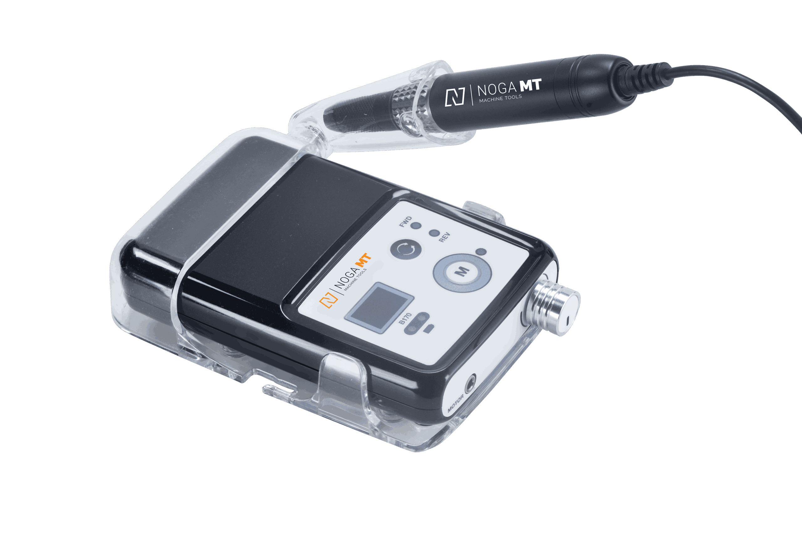
- Power pack & handpiece
- Speed control
- Compatible UFIBER tools
- Operating instructions
- Plug / adapter information
- Tool-specific RPM limits
Floating Dampers
Spring-loaded floating holders for controlled brush contact and automatic wear compensation in CNC and robotic finishing applications.
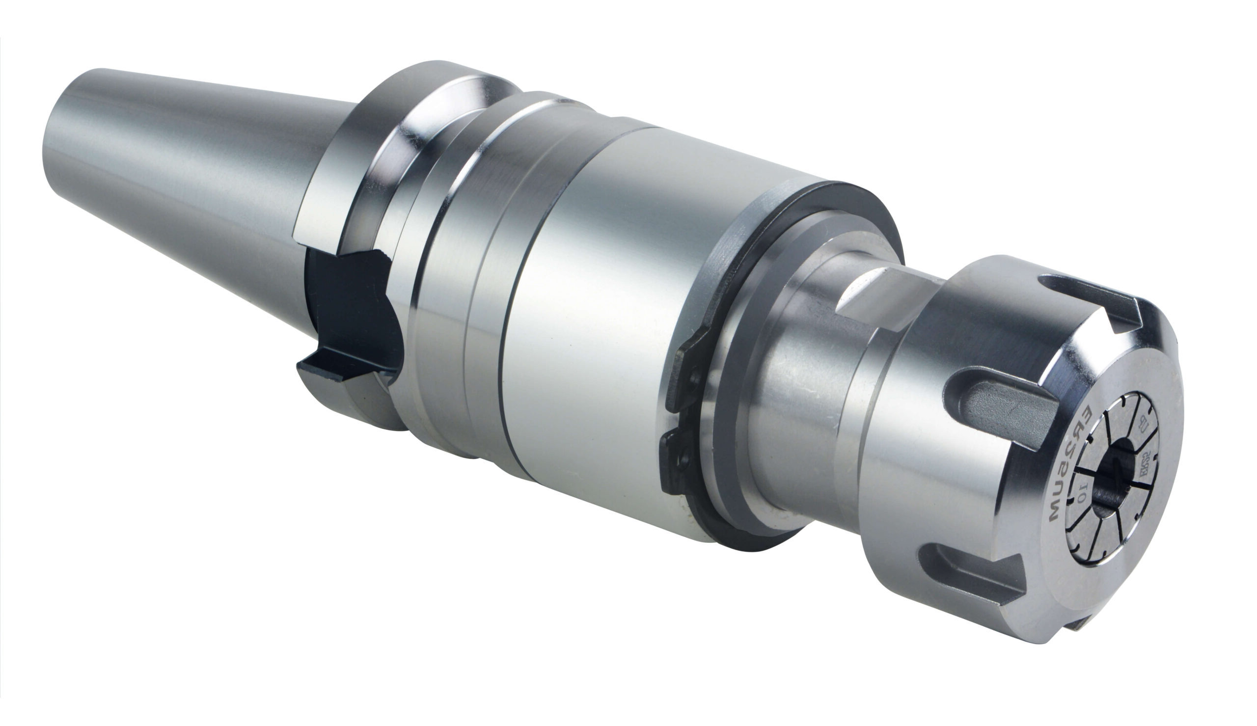
- BT30 / BT40 & End-Type models
- Stroke & spring force
- Maximum RPM
- Mounting & tool capacity
- Operating instructions
- Safety & usage guidelines
From Ceramic Brush Selection to Starting Parameters
Use this workflow specifically for UFIBER ceramic fiber brush applications.
Select Geometry
Choose Surface, Cross-Hole, End-Type or Point-Type according to the area the brush must reach.
Select Grit
Match grit to burr condition, workpiece material and required surface finish.
Set Parameters
Use the guide for recommended RPM, feed, depth of cut, projection, stroke and number of passes.
Validate & Optimize
Start conservatively, inspect the component and optimize the process on the actual workpiece.
Recommended Equipment by Ceramic Brush Family
This compatibility overview applies to UFIBER ceramic fiber brushes only.
| Brush Family | Machining Center | Lathe with Milling |
Lathe without Milling |
Dedicated Machine | Robot | Electric Rotary Tool |
Air-Powered Rotary Tool |
|---|---|---|---|---|---|---|---|
| Surface Brush | ✓ | ✓ | ✓ | ✓ | ✓ | — | — |
| Cross-Hole Brush | ✓ | — | — | ✓ | ✓ | — | — |
| End-Type Brush | ✓ | ✓ | ✓ | ✓ | ✓ | ✓ | ✓ |
| Point-Type Brush | ✓ | ✓ | ✓ | ✓ | ✓ | ✓ | ✓ |
✓ Recommended — Not recommended. Always follow the individual brush guide for mounting, speed and process limitations.
Ceramic Brush Technical Tools
Use these resources for UFIBER ceramic fiber brush selection, setup and application support.
UFIBER AI Assistant
Application-based starting guidance for UFIBER ceramic fiber brush geometry, grit and process direction.
Floating Dampers
Controlled compliance for CNC and robotic Surface Brush finishing applications.
UF9999 Portable E-Pack
Portable precision drive solution for UFIBER End-Type and Point-Type Brushes.
Case Studies
Review real applications, process examples and validated UFIBER use cases.
Catalogs & Literature
Download NOGA MT catalogs and supporting technical documentation.
Application Support
Send your material, burr condition, dimensions and machine details for technical assistance.
Not Sure Which UFIBER Tool, Grit or Starting Parameters to Use?
Start with the UFIBER AI Assistant or send NOGA your workpiece material, feature dimensions, burr condition, machine type and required finish. Final tool selection and machining parameters should always be validated on the actual component.