
UFIBER® Point Brush – Technical Specifications & Machining Guide
UFIBER® Point Brushes are compact ceramic-fiber tools designed for precision deburring, polishing and finishing in small bores, grooves, recesses, corners and other narrow or localized features.
Available in diameters from Ø1.0 to Ø3.0 mm for CNC machines, robotic systems and controlled hand-held rotary operation.
Features
Precision Access
Designed for accurate deburring, polishing and finishing in small, narrow and complex areas.
CNC & Robotic Ready
Suitable for automated machining on CNC machines, machining centers and robotic systems.
Ø1–3 mm Range
Five compact diameters provide controlled access to localized features and small bores.
Localized Finishing
Ideal for narrow bores, grooves, recesses, corners and detailed internal features.
Up to 12,000 RPM
Maximum spindle speed is 12,000 RPM when correctly mounted and securely operated.
Wide Grit Range
Supports controlled deburring through very fine polishing depending on material and finish requirements.
Point Brush Product Range
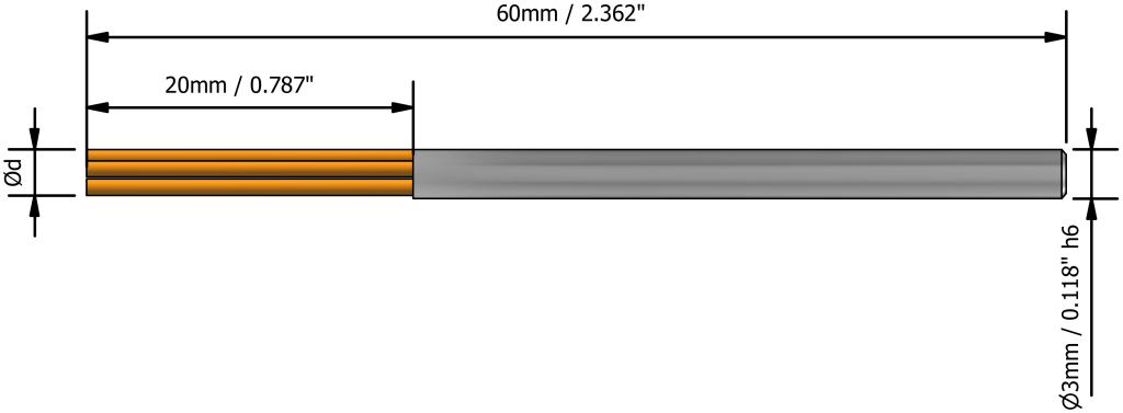
Dimensions for Ød=1.0-2.0mm (0.039-0.079″)
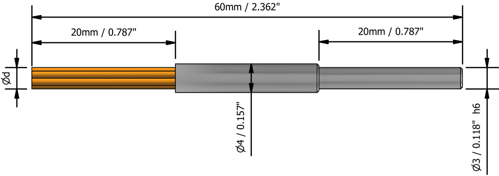
Dimensions for Ød=2.5-3.0mm (0.098-0.118″)
| Description | Diameter mm | Diameter inch | Maximum Spindle Speed |
|---|---|---|---|
| UF-PB-…-D1-L20 | Ø1.0 | 0.039" | 12,000 RPM |
| UF-PB-…-D1.5-L20 | Ø1.5 | 0.059" | 12,000 RPM |
| UF-PB-…-D2-L20 | Ø2.0 | 0.079" | 12,000 RPM |
| UF-PB-…-D2.5-L20 | Ø2.5 | 0.098" | 12,000 RPM |
| UF-PB-…-D3-L20 | Ø3.0 | 0.118" | 12,000 RPM |
Point Brush Application & Contact Methods
Axial Contact
Use the brush tip for localized finishing of recess bottoms, small flat areas and precise axial-contact applications.
Radial / Side Contact
Use controlled side contact for groove walls, bore walls and narrow internal surfaces. Avoid excessive lateral loading.
Angled / Localized Contact
Use light angled contact for corners, transitions and complex local features where direct axial access is limited.
Avoid Excessive Side Loading
Do not force the brush strongly against an edge or wall. Excessive lateral bending can reduce process stability and accelerate brush wear.
Grit Selection by Burr Condition & Material
| Grit | Code | Relative Action | Typical Application |
|---|---|---|---|
| #150 | G | Very aggressive | Heavy burrs and hardened materials |
| #200 | P | Aggressive | Hardened steels and difficult burrs |
| #400 | V | Medium-coarse | Steel, stainless steel and heat-resistant alloys |
| #600 | O | General deburring | General-purpose metal deburring |
| #800 | B | Fine deburring | Fine burr removal and pre-finishing |
| #1000 | W | Fine finishing | Controlled surface finishing |
| #1200 | R | Fine polishing | Final finishing and non-ferrous materials |
| #2000 | M | Very fine | Aluminum, plastics and delicate surfaces |
| #3000 | Z | Ultra-fine | Composites and high-finish applications |
| #6000 | A | Micro-finish | Final polishing of composites and plastics |
How to Use the UFIBER® Point Brush
1. Select the Diameter
Choose the smallest brush diameter that provides stable access and sufficient contact with the target feature.
2. Start with Light Engagement
Begin with minimum brush engagement. For Ø1.0 and Ø1.5 mm brushes, start at the lower end of the recommended feed and engagement ranges.
3. Maintain Controlled Movement
Keep the brush moving through the target area and avoid excessive side loading or prolonged contact at one point.
UFIBER® POINT BRUSH — MACHINING RECOMMENDATIONS
| Starting parameters for CNC deburring and polishing • Ø1–3 mm Point Brushes • Metric and imperial units • Use the lower value first and optimize on the actual component | ||||||||||||||
|---|---|---|---|---|---|---|---|---|---|---|---|---|---|---|
| WORKPIECE MATERIAL | DEBURRING | POLISHING | COOLANT | |||||||||||
| ISO | Material Group | Material Details | Condition | AISI / SAE / ASTM | DIN W.-Nr. | RPM | Feed mm/min | in/min | Brush Engagement mm | inch | UFIBER Deburring Grit | RPM | Feed mm/min | in/min | Brush Engagement mm | inch | UFIBER Polishing Grit | Recommended Method |
| P | Non-alloy steel and cast steel, free cutting steel | <0.25% C | Annealed | 1020 | 1.0044 | 8,000–12,000 | 250–500 9.8–19.7 | 0.03–0.10 0.001–0.004" | #400 (V) / #600 (O) #800 (B) for fine burrs | 8,000–12,000 | 180–400 7.1–15.7 | 0.02–0.06 0.001–0.002" | #800 (B) → #1200 (R) | Air / Wet |
| Non-alloy steel and cast steel, free cutting steel | ≥0.25% C | Annealed | 1035 | 1.0501 | 8,000–12,000 | 250–500 9.8–19.7 | 0.03–0.10 0.001–0.004" | #400 (V) / #600 (O) #800 (B) for fine burrs | 8,000–12,000 | 180–400 7.1–15.7 | 0.02–0.06 0.001–0.002" | #800 (B) → #1200 (R) | Air / Wet | |
| Non-alloy steel and cast steel, free cutting steel | <0.55% C | Quenched and tempered | 1045 | 1.1201 | 7,000–10,000 | 200–450 7.9–17.7 | 0.03–0.09 0.001–0.004" | #150 / #200 / #400 #150 heavy • #200 general • #400 controlled | 7,000–10,000 | 150–350 5.9–13.8 | 0.02–0.05 0.001–0.002" | #400 → #800 #1000 / #1200 final | Air / Wet | |
| Non-alloy steel and cast steel, free cutting steel | ≥0.55% C | Annealed | 1055 | 1.0535 | 7,000–10,000 | 200–450 7.9–17.7 | 0.03–0.09 0.001–0.004" | #150 / #200 / #400 #150 heavy • #200 general • #400 controlled | 7,000–10,000 | 150–350 5.9–13.8 | 0.02–0.05 0.001–0.002" | #400 → #800 #1000 / #1200 final | Air / Wet | |
| Non-alloy steel and cast steel, free cutting steel | ≥0.55% C | Quenched and tempered | 1060 | 1.1221 | 6,000–9,000 | 180–400 7.1–15.7 | 0.03–0.08 0.001–0.003" | #150 / #200 / #400 | 6,000–9,000 | 120–300 4.7–11.8 | 0.02–0.05 0.001–0.002" | #400 → #800 #1000 / #1200 final | Air / Wet | |
| Low alloy and cast steel (<5% alloying elements) | — | Annealed | G92600 | 1.5028 | 7,000–10,000 | 200–450 7.9–17.7 | 0.03–0.09 0.001–0.004" | #400 / #600 | 7,000–10,000 | 150–350 5.9–13.8 | 0.02–0.06 0.001–0.002" | #800 → #1200 | Air / Wet | |
| Low alloy and cast steel (<5% alloying elements) | — | Quenched and tempered | 4130 | 1.7218 | 6,000–9,000 | 180–400 7.1–15.7 | 0.03–0.08 0.001–0.003" | #150 / #200 / #400 | 6,000–9,000 | 120–300 4.7–11.8 | 0.02–0.05 0.001–0.002" | #400 → #800 #1000 / #1200 final | Air / Wet | |
| Low alloy and cast steel (<5% alloying elements) | — | Quenched and tempered | 4142 | 1.2332 | 6,000–9,000 | 180–400 7.1–15.7 | 0.03–0.08 0.001–0.003" | #150 / #200 / #400 | 6,000–9,000 | 120–300 4.7–11.8 | 0.02–0.05 0.001–0.002" | #400 → #800 #1000 / #1200 final | Air / Wet | |
| Low alloy and cast steel (<5% alloying elements) | — | Quenched and tempered | 5045 | 1.7006 | 6,000–9,000 | 180–400 7.1–15.7 | 0.03–0.08 0.001–0.003" | #150 / #200 / #400 | 6,000–9,000 | 120–300 4.7–11.8 | 0.02–0.05 0.001–0.002" | #400 → #800 #1000 / #1200 final | Air / Wet | |
| High alloyed steel, cast steel and tool steel | — | Annealed | H13 | 1.2344 | 5,000–8,000 | 150–350 5.9–13.8 | 0.03–0.07 0.001–0.003" | #150 / #200 / #400 | 5,000–8,000 | 120–280 4.7–11.0 | 0.02–0.05 0.001–0.002" | #400 → #800 #1000 / #1200 final | Wet preferred | |
| High alloyed steel, cast steel and tool steel | — | Quenched and tempered | M33 | 1.3249 | 5,000–8,000 | 150–350 5.9–13.8 | 0.03–0.07 0.001–0.003" | #150 / #200 / #400 | 5,000–8,000 | 120–280 4.7–11.0 | 0.02–0.05 0.001–0.002" | #400 → #800 #1000 / #1200 final | Wet preferred | |
| Stainless steel and cast steel | Ferritic / martensitic | — | 420 | 1.4021 | 6,000–9,000 | 180–400 7.1–15.7 | 0.03–0.08 0.001–0.003" | #150 / #200 / #400 | 6,000–9,000 | 150–320 5.9–12.6 | 0.02–0.05 0.001–0.002" | #400 → #800 #1000 / #1200 final | Wet preferred | |
| Stainless steel and cast steel | Martensitic | — | — | — | 5,000–8,000 | 150–350 5.9–13.8 | 0.03–0.07 0.001–0.003" | #150 / #200 / #400 | 5,000–8,000 | 120–280 4.7–11.0 | 0.02–0.05 0.001–0.002" | #400 → #800 #1000 / #1200 final | Wet preferred | |
| M | Stainless steel | Austenitic, duplex | — | 304L | 1.4306 | 7,000–10,000 | 180–400 7.1–15.7 | 0.03–0.08 0.001–0.003" | #400 / #600 #800 for fine burrs | 7,000–10,000 | 150–350 5.9–13.8 | 0.02–0.06 0.001–0.002" | #800 → #1200 | Wet recommended |
| K | Gray cast iron (GG) | Ferritic / pearlitic | — | Class 25 | 0.6015 | 7,000–10,000 | 200–450 7.9–17.7 | 0.03–0.09 0.001–0.004" | #200 / #400 #600 for fine burrs | 7,000–10,000 | 150–350 5.9–13.8 | 0.02–0.06 0.001–0.002" | #600 → #1000 | Air preferred |
| Gray cast iron (GG) | Pearlitic / martensitic | — | Grade H20 | 36037 | 6,000–9,000 | 180–400 7.1–15.7 | 0.03–0.08 0.001–0.003" | #150 / #200 / #400 | 6,000–9,000 | 120–300 4.7–11.8 | 0.02–0.05 0.001–0.002" | #400 → #800 #1000 / #1200 final | Air preferred | |
| Nodular cast iron (GGG) | Ferritic | — | 60-40-18 | 0.7043 | 7,000–10,000 | 220–480 8.7–18.9 | 0.03–0.10 0.001–0.004" | #400 / #600 | 7,000–10,000 | 160–350 6.3–13.8 | 0.02–0.06 0.001–0.002" | #800 → #1200 | Air preferred | |
| Nodular cast iron (GGG) | Pearlitic | — | F33500 | 0.705 | 6,000–9,000 | 180–400 7.1–15.7 | 0.03–0.08 0.001–0.003" | #150 / #200 / #400 | 6,000–9,000 | 120–300 4.7–11.8 | 0.02–0.05 0.001–0.002" | #400 → #800 #1000 / #1200 final | Air preferred | |
| Malleable cast iron | Ferritic | — | A47 | 0.8135 | 7,000–10,000 | 220–480 8.7–18.9 | 0.03–0.10 0.001–0.004" | #400 / #600 | 7,000–10,000 | 160–350 6.3–13.8 | 0.02–0.06 0.001–0.002" | #800 → #1200 | Air preferred | |
| Malleable cast iron | Pearlitic | — | A220 Class | 0.8155 | 6,000–9,000 | 180–400 7.1–15.7 | 0.03–0.08 0.001–0.003" | #150 / #200 / #400 | 6,000–9,000 | 120–300 4.7–11.8 | 0.02–0.05 0.001–0.002" | #400 → #800 #1000 / #1200 final | Air preferred | |
| N | Aluminum-wrought alloys | — | Not hardenable | 5005 | 3.3315 | 9,000–12,000 | 300–600 11.8–23.6 | 0.02–0.08 0.001–0.003" | #800 / #1200 | 9,000–12,000 | 250–500 9.8–19.7 | 0.02–0.05 0.001–0.002" | #1200 → #2000 | Wet / MQL |
| Aluminum-wrought alloys | — | Hardenable | 7075 | 3.4365 | 9,000–12,000 | 300–600 11.8–23.6 | 0.02–0.08 0.001–0.003" | #800 / #1200 | 9,000–12,000 | 250–500 9.8–19.7 | 0.02–0.05 0.001–0.002" | #1200 → #2000 | Wet / MQL | |
| Aluminum-cast alloys | ≤12% Si | Not hardenable | 518 | 3.3292 | 9,000–12,000 | 300–600 11.8–23.6 | 0.02–0.08 0.001–0.003" | #800 / #1200 | 9,000–12,000 | 250–500 9.8–19.7 | 0.02–0.05 0.001–0.002" | #1200 → #2000 | Wet / MQL | |
| Aluminum-cast alloys | ≤12% Si | Hardenable | 515 | 3.3241 | 8,000–11,000 | 280–550 11.0–21.7 | 0.02–0.08 0.001–0.003" | #800 / #1200 | 8,000–11,000 | 220–450 8.7–17.7 | 0.02–0.05 0.001–0.002" | #1200 → #2000 | Wet / MQL | |
| Aluminum-cast alloys | >12% Si | High temperature | 390 | — | 8,000–11,000 | 220–450 8.7–17.7 | 0.02–0.07 0.001–0.003" | #600 / #800 | 7,000–10,000 | 180–400 7.1–15.7 | 0.02–0.05 0.001–0.002" | #1000 → #1200 | Wet / MQL | |
| Copper alloys | >1% Pb | Free cutting | C36000 | 2.0375 | 8,000–12,000 | 250–500 9.8–19.7 | 0.02–0.08 0.001–0.003" | #800 / #1200 | 8,000–12,000 | 200–400 7.9–15.7 | 0.02–0.05 0.001–0.002" | #1200 → #2000 | Air / Wet | |
| Copper alloys | — | Brass | C22000 | 2.023 | 8,000–12,000 | 250–500 9.8–19.7 | 0.02–0.08 0.001–0.003" | #800 / #1200 | 8,000–12,000 | 200–400 7.9–15.7 | 0.02–0.05 0.001–0.002" | #1200 → #2000 | Air / Wet | |
| Copper alloys | — | Electrolytic copper | C63000 | 2.0966 | 8,000–11,000 | 220–450 8.7–17.7 | 0.02–0.07 0.001–0.003" | #800 / #1200 | 7,000–10,000 | 180–400 7.1–15.7 | 0.02–0.05 0.001–0.002" | #1200 → #2000 | Air / Wet | |
| Non-metallic | Duroplastics, fiber plastics | — | Bakelite | — | 6,000–9,000 | 200–450 7.9–17.7 | 0.02–0.07 0.001–0.003" | #2000 / #3000 | 5,000–8,000 | 150–350 5.9–13.8 | 0.02–0.05 0.001–0.002" | #3000 → #6000 | Dry air + extraction | |
| Non-metallic | Hard rubber | — | Ebonite | — | 5,000–8,000 | 180–400 7.1–15.7 | 0.02–0.07 0.001–0.003" | #2000 / #3000 | 5,000–8,000 | 150–350 5.9–13.8 | 0.02–0.05 0.001–0.002" | #3000 → #6000 | Dry air + extraction | |
| S | High temperature alloys | Fe based | Annealed | 330 | 1.4864 | 6,000–9,000 | 150–350 5.9–13.8 | 0.03–0.08 0.001–0.003" | #150 / #200 / #400 | 6,000–9,000 | 120–300 4.7–11.8 | 0.02–0.05 0.001–0.002" | #400 → #800 #1000 / #1200 final | Wet recommended |
| High temperature alloys | Fe based | Hardened | S590 | 1.4977 | 5,000–8,000 | 130–300 5.1–11.8 | 0.03–0.07 0.001–0.003" | #150 / #200 / #400 | 5,000–8,000 | 100–250 3.9–9.8 | 0.02–0.05 0.001–0.002" | #400 → #800 #1000 / #1200 final | Wet recommended | |
| High temperature alloys | Ni or Co based | Annealed | Incoloy 825 | 2.4858 | 5,000–8,000 | 120–300 4.7–11.8 | 0.03–0.07 0.001–0.003" | #150 / #200 / #400 | 5,000–8,000 | 100–250 3.9–9.8 | 0.02–0.05 0.001–0.002" | #400 → #800 #1000 / #1200 final | Wet recommended | |
| High temperature alloys | Ni or Co based | Hardened | Inconel 718 | 2.4668 | 5,000–8,000 | 120–280 4.7–11.0 | 0.03–0.07 0.001–0.003" | #150 / #200 / #400 | 5,000–8,000 | 100–240 3.9–9.4 | 0.02–0.05 0.001–0.002" | #400 → #800 #1000 / #1200 final | Wet recommended | |
| High temperature alloys | Ni or Co based | Cast | Nimocast K24 | 2.4674 | 5,000–8,000 | 120–280 4.7–11.0 | 0.03–0.07 0.001–0.003" | #150 / #200 / #400 | 5,000–8,000 | 100–240 3.9–9.4 | 0.02–0.05 0.001–0.002" | #400 → #800 #1000 / #1200 final | Wet recommended | |
| Titanium alloys | — | Pure | Titanium G.1 | 3.7024 | 5,000–8,000 | 140–320 5.5–12.6 | 0.03–0.07 0.001–0.003" | #150 / #200 / #400 | 5,000–8,000 | 110–260 4.3–10.2 | 0.02–0.05 0.001–0.002" | #400 → #800 #1000 / #1200 final | Wet recommended | |
| Titanium alloys | — | Alpha+beta alloys, hardened | Titanium G.5 | 3.7165 | 5,000–8,000 | 120–280 4.7–11.0 | 0.03–0.07 0.001–0.003" | #150 / #200 / #400 | 5,000–8,000 | 100–240 3.9–9.4 | 0.02–0.05 0.001–0.002" | #400 → #800 #1000 / #1200 final | Wet recommended | |
| H | Hardened steel | — | Hardened | HARDOX 500 | — | 5,000–8,000 | 120–300 4.7–11.8 | 0.03–0.07 0.001–0.003" | #150 / #200 / #400 | 5,000–8,000 | 100–250 3.9–9.8 | 0.02–0.05 0.001–0.002" | #400 → #800 #1000 / #1200 final | Wet preferred |
| Hardened steel | — | Hardened | HARDOX Extreme | — | 5,000–8,000 | 100–250 3.9–9.8 | 0.03–0.06 0.001–0.002" | #150 / #200 / #400 | 5,000–8,000 | 90–220 3.5–8.7 | 0.02–0.04 0.001–0.002" | #400 → #800 #1000 / #1200 final | Wet preferred | |
| Chilled cast iron | — | Cast | A532 IIIA 25% Cr | 0.965 | 5,000–8,000 | 120–300 4.7–11.8 | 0.03–0.07 0.001–0.003" | #150 / #200 / #400 | 5,000–8,000 | 100–250 3.9–9.8 | 0.02–0.05 0.001–0.002" | #400 → #800 #1000 / #1200 final | Wet preferred | |
| Hardened cast iron | — | Hardened | A532 IID 20% CrMo | 0.9645 | 5,000–8,000 | 100–250 3.9–9.8 | 0.03–0.06 0.001–0.002" | #150 / #200 / #400 | 5,000–8,000 | 90–220 3.5–8.7 | 0.02–0.04 0.001–0.002" | #400 → #800 #1000 / #1200 final | Wet preferred | |
Controlling Deburring & Polishing Performance
Increase Deburring Action
Coarser grit → slightly greater engagement → lower feed → additional controlled pass
Reduce Aggressiveness
Finer grit → lighter engagement → higher feed → fewer passes
Improve Surface Finish
Finer grit sequence → light contact → stable feed → controlled finishing passes
Improve Brush Life
Reduce side loading → use minimum required engagement → maintain correct alignment
Point Brush Troubleshooting
| Problem | Recommended Adjustment |
|---|---|
| Burr remains | Use a coarser grit → slightly increase engagement → reduce feed → add another controlled pass. |
| Excessive edge rounding | Increase feed → reduce brush engagement → select a finer grit → reduce RPM if necessary. |
| Brush marks | Use a finer grit → reduce engagement → maintain a stable finishing feed → add a light final pass. |
| Excessive brush wear | Reduce engagement → check alignment → minimize side loading → verify runout and clamping. |
| Poor surface finish | Use a progressive grit sequence → lighter final engagement → stable feed → verify brush cleanliness. |
| Vibration / unstable contact | Stop operation → check chuck, runout, brush condition and workholding before restarting. |
Brush Wear & Maintenance
Brush Wear Changes Cutting Behavior
As the ceramic fibers wear and become shorter, brush stiffness and contact behavior may change. Re-check the process when the brush has visibly shortened.
Compensate Gradually
If the process becomes too aggressive, reduce brush engagement, increase feed, reduce RPM if required, or move to a finer grit.
Keep the Brush Clean
Remove accumulated machining debris, dust and coolant residue. Contamination can reduce consistency and surface-finish quality.
Inspect Before Production
Check the brush tip, shank, clamping condition and runout before use. Replace a damaged or unstable brush before production machining.
Point Brush Installation & Usage
01. Shank Grip
Grip the brush shank by at least 20 mm to ensure secure clamping.
02. Chuck Matching
Use a chuck or collet that correctly matches the brush shank diameter.
03. Minimize Runout
Keep spindle and tool runout as low as practical for stable contact.
04. Initial Engagement
Begin with minimum contact and increase engagement gradually only when required.
05. Secure Workholding
Ensure the brush and workpiece are securely clamped before CNC operation.
06. Validate the Process
Confirm the selected parameters on the actual component before production use.
Manual & CNC Operating Speed Guidelines
Manual Operation
1,000 → 3,000 RPM
Start at approximately 1,000 RPM. Once stable control is established, increase gradually up to 3,000 RPM. Speeds above 3,000 RPM are not recommended for hand-held operation.
Automated Operation
Up to 12,000 RPM
For securely clamped CNC or robotic applications, follow the machining recommendation table and never exceed 12,000 RPM.
Point Brush Safety Precautions & Instructions
Operation Safety
• Do not exceed the specified maximum spindle speed.
• Do not use pneumatic-powered hand tools.
• Stop immediately if abnormal vibration occurs.
• Avoid prolonged machining at one fixed point.
• Avoid excessive side loading.
Operator & Work Area Safety
• Wear suitable eye, skin and respiratory protection.
• Use suitable dust and particle extraction.
• Keep flammable materials away from the machining area.
• Ensure secure workholding and controlled access to the work area.