UFIBER® SURFACE BRUSH – Technical Information & Application Guide
Technical data for CNC, robotic and automated surface deburring, edge finishing and polishing. Includes mounting options, grit selection, starting machining parameters, an RPM calculator, safety guidance and 3D models.
Suitable for machining centers, CNC equipment and robotic systems across steel, stainless steel, aluminum, heat-resistant alloys, cast iron, composites and resin materials.
Features
A cleaner hierarchy replaces the current long text wall while preserving the technical intent of the live page.
Uniform Surface Finish
Designed for controlled polishing and deburring on flat surfaces and broad geometries.
CNC & Robotic Ready
Sleeve and shank mounting support automated deburring in CNC machines, machining centers and robotic systems.
Ceramic Cutting Edges
Ceramic fibers continuously expose cutting edges for controlled material removal rather than wire-brush smearing.
Adjustable Projection
Projection can be tuned as the brush wears to balance flexibility, cutting pressure and surface finish.
Cross-hole Capability
With the appropriate shank, centrifugal expansion can also remove fine burrs inside cylindrical intersections.
Wide Grit Range
Available from coarse deburring grits to ultra-fine polishing grades for different materials and finish requirements.
Surface Brush Product Range
Dimensions, spare parts and starting operating limits in metric and imperial units.

Surface Brush Product Range
Dimensions, spare parts and starting operating limits in metric and imperial units.
| Brush Ød | ØDS | L | L2 | Clamping Screw / SKU | LN Key / SKU | Weight | DOC Polishing | DOC Deburring | DOC Max. | Recommended RPM | Max. Feed | Max. Projection |
|---|---|---|---|---|---|---|---|---|---|---|---|---|
| Ø60.236″ | N/A | 301.181″ | 42.51.673″ | N/A | N/A | 3 g | 0.2 mm0.008″ | 0.5 mm0.020″ | 1.2 mm0.050″ | 9,000–12,000 | 2,000 mm/min79 in/min | 10 mm0.394″ |
| Ø150.590″ | Ø60.236″ | 501.969″ | 652.559″ | M3×0.5×4 UF0019 |
1.5 DH0005 |
7 g | 5,700–7,200 | |||||
| Ø250.984″ | Ø90.354″ | 752.952″ | 1003.937″ | M4×0.7×8 UF0018 |
2.0 UF0020 |
21 g | 5,000–6,000 | |||||
| Ø401.575″ | Ø120.472″ | 752.952″ | 963.780″ | M6×1.0×16 UF0017 |
3.0 DB0007 |
26 g | 2,700–3,600 | |||||
| Ø602.362″ | Ø130.512″ | 752.952″ | 963.780″ | M6×1.0×20 UF0016 |
3.0 DB0007 |
70 g | 1,800–2,400 | |||||
| Ø1003.937″ | Ø160.630″ | 752.952″ | 973.820″ | M6×1.0×25 UF0015 |
3.0 DB0007 |
140 g | 1,000–1,400 |
Mounting Options
Mount the surface brush in a standard collet/chuck using either the corresponding sleeve or the direct shank connection.
With Sleeve
Recommended when higher stability and consistent contact pressure are required. The sleeve reinforces the brush base during high-speed CNC or robotic operation.
Without Sleeve / Direct Shank
Use the appropriate shank size specified by ØDS. Verify the matching clamping screw and LN key before operation.
Surface Brush Sleeves & Spare Parts

Surface Brush Sleeves & Spare Parts
Sleeves reinforce the brush base and provide stable mounting for CNC and automated applications.
| Brush | SKU | Description | Ød1 External | ØDS | L1 | L2 | Weight | Clamping Screw | Screw SKU | LN Key | Key SKU |
|---|---|---|---|---|---|---|---|---|---|---|---|
| Ø6 / 0.236″ | UF5506 | UF-FS-6-C06-L70 | 10 / 0.394″ | Ø6 / 0.236″ | 30 / 1.181″ | 71 / 2.795″ | 30 g | M3×0.5×4 | UF0010 | 2.5 | UF0021 |
| Ø15 / 0.590″ | UF5515 | UF-FS-15-C06-L90 | 18.5 / 0.728″ | Ø6 / 0.236″ | 30 / 1.181″ | 92 / 3.622″ | 40 g | M3×0.5×6 | UF0011 | 2 | UF0020 |
| Ø25 / 0.984″ | UF5525 | UF-FS-25-C10-L140 | 30 / 1.181″ | Ø10 / 0.394″ | 30 / 1.181″ | 149 / 5.866″ | 160 g | M4×0.7×10 | UF0012 | 2.5 | UF0021 |
| Ø40 / 1.575″ | UF5540 | UF-FS-40-C12-L140 | 45 / 1.772″ | Ø12 / 0.472″ | 30 / 1.181″ | 135 / 5.315″ | 200 g | M6×1.0×10 | UF0013 | 4 | UF0022 |
| Ø60 / 2.362″ | UF5560 | UF-FS-60-C12-L145 | 67 / 2.638″ | Ø12 / 0.472″ | 40 / 1.575″ | 145 / 5.708″ | 320 g | M6×1.0×10 | UF0013 | 4 | UF0022 |
| Ø100 / 3.937″ | UF5500 | UF-FS-100-C16-L155 | 110 / 4.330″ | Ø16 / 0.630″ | 40 / 1.575″ | 155 / 6.102″ | 670 g | M8×1.25×16 | UF0014 | 5 | UF0023 |
Surface Brush Shanks
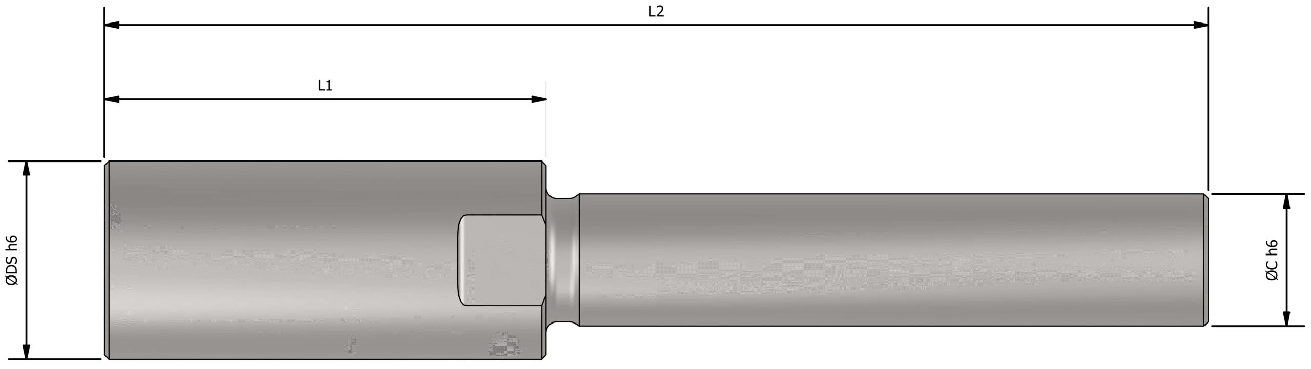
Surface Brush Shanks
Direct shank options for mounting the Surface Brush without a sleeve.
| Suitable Brush | SKU | Description | ØDS | L1 | L2 | ØC |
|---|---|---|---|---|---|---|
| Ø15 / 0.590″ | UF5001 | UF S-L045-DS06-C06 | 6 / 0.236″ | 30 / 1.181″ | 45 / 1.771″ | 6 / 0.236″ |
| Ø25 / 0.984″ | UF5002 | UF S-L050-DS09-C06 | 9 / 0.354″ | 50 / 1.968″ | — | 6 / 0.236″ |
| UF5003 | UF S-L050-DS09-C10 | 9 / 0.354″ | 50 / 1.968″ | — | 10 / 0.398″ | |
| UF5007 | UF-S-L120-DS09-C10 | 9 / 0.354″ | 120 / 4.724″ | — | 10 / 0.398″ | |
| Ø40 / 1.575″ | UF5004 | UF S-L050-DS12-C12 | 12 / 0.472″ | 50 / 1.968″ | — | 12 / 0.472″ |
| UF5008 | UF-S-L120-DS12-C12 | 12 / 0.472″ | 120 / 4.724″ | — | 12 / 0.472″ | |
| Ø60 / 2.362″ | UF5005 | UF S-L050-DS13-C12 | 13 / 0.512″ | 50 / 1.968″ | — | 12 / 0.472″ |
| Ø100 / 3.937″ | UF5006 | UF S-L050-DS16-C16 | 16 / 0.630″ | 50 / 1.968″ | — | 16 / 0.630″ |
Grit Selection by Burr Condition & Material
Choose coarse grits for heavier burrs and progressively finer grits for controlled edge finishing and polishing.
Brush Selection Guide

How to Use the UFIBER® Surface Brush
Five practical rules for stable cutting action, controlled wear and cross-hole use.
Feed direction
For side-burr removal, use an up-cut approach so the ceramic fibers work against the burr from underneath rather than laying it over.

Adjust brush projection as it wears
Longer fibers are more flexible and gentler. As the fibers become shorter, they become more rigid, so reduce aggressiveness or adjust the brush projection and machining conditions to maintain a controlled finish.

Step differences & uneven surfaces
If a step causes excessive brush bending, lower the brush vertically without rotation first. Reduce the depth of cut and increase the feed as needed to avoid excessive local loading.
Precision slit burr removal
Process in both directions where necessary. If burrs are displaced into a slit, reverse the processing direction so the ceramic fibers face the burr directly and remove it, rather than pushing it farther into the slit.
Cross-hole capability
The Surface Brush can also expand inside a cylindrical bore by centrifugal force and remove fine cross-hole burrs. Start with #1200 for greater flexibility; if burrs remain, try #1000 for stronger cutting action.

UFIBER® Surface Brush — Machining Recommendations
Starting parameters for CNC deburring and polishing • Metric and imperial units • Use the lower value first and optimize on the actual component.
Complete material-by-material starting parameters for deburring and polishing. Use the filters or search box to quickly find an ISO group, alloy or grade.
| WORKPIECE MATERIAL | DEBURRING | POLISHING | COOLANT Recommended Method |
||||||||||
|---|---|---|---|---|---|---|---|---|---|---|---|---|---|
| ISO | Material Group | Material Details | Condition | AISI / SAE / ASTM DIN W.-Nr. |
Vc Metric / Imperial |
Feed Metric / Imperial |
DOC Metric / Imperial |
UFIBER Deburring Grit | Vc Metric / Imperial |
Feed Metric / Imperial |
DOC Metric / Imperial |
UFIBER Polishing Grit | |
| P | Non-alloy steel and cast steel, free cutting steel | <0.25% C | Annealed | 10201.0044 | 170–315 m/min558–1033 sfm | 1200–2000 mm/min47.2–78.7 in/min | 0.3–0.5 mm0.012–0.020 in | #400 (V) / #600 (O) #800 (B) for fine burrs | 165–310 m/min541–1017 sfm | 700–1400 mm/min27.6–55.1 in/min | 0.1–0.2 mm0.004–0.008 in | #800 (B) → #1200 (R) | Air / Wet |
| P | Non-alloy steel and cast steel, free cutting steel | ≥0.25% C | Annealed | 10351.0501 | 115–315 m/min377–1033 sfm | 1200–2000 mm/min47.2–78.7 in/min | 0.3–0.5 mm0.012–0.020 in | #400 (V) / #600 (O) #800 (B) for fine burrs | 165–300 m/min541–984 sfm | 700–1400 mm/min27.6–55.1 in/min | 0.1–0.2 mm0.004–0.008 in | #800 (B) → #1200 (R) | — |
| P | Non-alloy steel and cast steel, free cutting steel | <0.55% C | Quenched and tempered | 10451.1201 | 100–270 m/min328–886 sfm | 1000–1700 mm/min39.4–66.9 in/min | 0.25–0.45 mm0.010–0.018 in | #150 (G) / #200 (P) / #400 (V) #150 heavy burr • #200 general • #400 controlled edge | 140–260 m/min459–853 sfm | 600–1100 mm/min23.6–43.3 in/min | 0.08–0.18 mm0.003–0.007 in | #400 (V) → #800 (B) #1000 (W) / #1200 (R) final | — |
| P | Non-alloy steel and cast steel, free cutting steel | ≥0.55% C | Annealed | 10551.0535 | 95–270 m/min312–886 sfm | 1000–1700 mm/min39.4–66.9 in/min | 0.25–0.45 mm0.010–0.018 in | #150 (G) / #200 (P) / #400 (V) #150 heavy burr • #200 general • #400 controlled edge | 150–280 m/min492–919 sfm | 600–1100 mm/min23.6–43.3 in/min | 0.08–0.18 mm0.003–0.007 in | #400 (V) → #800 (B) #1000 (W) / #1200 (R) final | — |
| P | Non-alloy steel and cast steel, free cutting steel | ≥0.55% C | Quenched and tempered | 10601.1221 | 80–230 m/min262–755 sfm | 1000–1700 mm/min39.4–66.9 in/min | 0.25–0.45 mm0.010–0.018 in | #150 (G) / #200 (P) / #400 (V) #150 heavy burr • #200 general • #400 controlled edge | 120–230 m/min394–755 sfm | 600–1100 mm/min23.6–43.3 in/min | 0.08–0.18 mm0.003–0.007 in | #400 (V) → #800 (B) #1000 (W) / #1200 (R) final | — |
| P | Low alloy and cast steel (less than 5% of alloying elements) | — | Annealed | G926001.5028 | 95–235 m/min312–771 sfm | 1000–1800 mm/min39.4–70.9 in/min | 0.25–0.5 mm0.010–0.020 in | #400 (V) / #600 (O) | 165–250 m/min541–820 sfm | 600–1200 mm/min23.6–47.2 in/min | 0.08–0.2 mm0.003–0.008 in | #800 (B) → #1200 (R) | — |
| P | Low alloy and cast steel (less than 5% of alloying elements) | — | Quenched and tempered | 41301.7218 | 80–200 m/min262–656 sfm | 1000–1800 mm/min39.4–70.9 in/min | 0.25–0.5 mm0.010–0.020 in | #150 (G) / #200 (P) / #400 (V) #150 heavy burr • #200 general • #400 controlled edge | 130–220 m/min427–722 sfm | 600–1200 mm/min23.6–47.2 in/min | 0.08–0.2 mm0.003–0.008 in | #400 (V) → #800 (B) #1000 (W) / #1200 (R) final | — |
| P | Low alloy and cast steel (less than 5% of alloying elements) | — | Quenched and tempered | 41421.2332 | 80–200 m/min262–656 sfm | 1000–1800 mm/min39.4–70.9 in/min | 0.25–0.5 mm0.010–0.020 in | #150 (G) / #200 (P) / #400 (V) #150 heavy burr • #200 general • #400 controlled edge | 130–220 m/min427–722 sfm | 600–1200 mm/min23.6–47.2 in/min | 0.08–0.2 mm0.003–0.008 in | #400 (V) → #800 (B) #1000 (W) / #1200 (R) final | — |
| P | Low alloy and cast steel (less than 5% of alloying elements) | — | Quenched and tempered | 50451.7006 | 80–200 m/min262–656 sfm | 1000–1800 mm/min39.4–70.9 in/min | 0.25–0.5 mm0.010–0.020 in | #150 (G) / #200 (P) / #400 (V) #150 heavy burr • #200 general • #400 controlled edge | 130–220 m/min427–722 sfm | 600–1200 mm/min23.6–47.2 in/min | 0.08–0.2 mm0.003–0.008 in | #400 (V) → #800 (B) #1000 (W) / #1200 (R) final | — |
| P | High alloyed steel, cast steel and tool steel | — | Annealed | H131.2344 | 60–150 m/min197–492 sfm | 700–1400 mm/min27.6–55.1 in/min | 0.2–0.4 mm0.008–0.016 in | #150 (G) / #200 (P) / #400 (V) #150 heavy burr • #200 general • #400 controlled edge | 350–400 m/min1148–1312 sfm | 400–800 mm/min15.7–31.5 in/min | 0.05–0.2 mm0.002–0.008 in | #400 (V) → #800 (B) #1000 (W) / #1200 (R) final | Wet preferred |
| P | High alloyed steel, cast steel and tool steel | — | Quenched and tempered | M331.3249 | 50–120 m/min164–394 sfm | 700–1400 mm/min27.6–55.1 in/min | 0.2–0.4 mm0.008–0.016 in | #150 (G) / #200 (P) / #400 (V) #150 heavy burr • #200 general • #400 controlled edge | 250–350 m/min820–1148 sfm | 400–800 mm/min15.7–31.5 in/min | 0.05–0.2 mm0.002–0.008 in | #400 (V) → #800 (B) #1000 (W) / #1200 (R) final | — |
| P | Stainless steel and cast steel | Ferritic/martensitic | — | 4201.4021 | 60–140 m/min197–459 sfm | 800–1500 mm/min31.5–59.1 in/min | 0.2–0.4 mm0.008–0.016 in | #150 (G) / #200 (P) / #400 (V) #150 heavy burr • #200 general • #400 controlled edge | 150–220 m/min492–722 sfm | 600–1200 mm/min23.6–47.2 in/min | 0.05–0.2 mm0.002–0.008 in | #400 (V) → #800 (B) #1000 (W) / #1200 (R) final | Wet recommended |
| P | Stainless steel and cast steel | Martensitic | — | —— | 50–120 m/min164–394 sfm | 800–1500 mm/min31.5–59.1 in/min | 0.2–0.4 mm0.008–0.016 in | #150 (G) / #200 (P) / #400 (V) #150 heavy burr • #200 general • #400 controlled edge | 120–200 m/min394–656 sfm | 600–1200 mm/min23.6–47.2 in/min | 0.05–0.2 mm0.002–0.008 in | #400 (V) → #800 (B) #1000 (W) / #1200 (R) final | — |
| M | Stainless steel | Austenitic, duplex | — | 304L1.4306 | 50–120 m/min164–394 sfm | 800–1500 mm/min31.5–59.1 in/min | 0.2–0.4 mm0.008–0.016 in | #400 (V) / #600 (O) #800 (B) for fine burrs | 150–250 m/min492–820 sfm | 600–1200 mm/min23.6–47.2 in/min | 0.05–0.2 mm0.002–0.008 in | #800 (B) → #1200 (R) | Wet recommended |
| K | Gray cast iron (GG) | Ferritic / pearlitic | — | Class 250.6015 | 60–170 m/min197–558 sfm | 900–1600 mm/min35.4–63.0 in/min | 0.25–0.45 mm0.010–0.018 in | #200 (P) / #400 (V) #600 (O) for fine burrs | 120–220 m/min394–722 sfm | 600–1100 mm/min23.6–43.3 in/min | 0.08–0.18 mm0.003–0.007 in | #600 (O) → #1000 (W) | Air preferred |
| K | Gray cast iron (GG) | Pearlitic / martensitic | — | Grade H2036037 | 50–140 m/min164–459 sfm | 900–1600 mm/min35.4–63.0 in/min | 0.25–0.45 mm0.010–0.018 in | #150 (G) / #200 (P) / #400 (V) #150 heavy burr • #200 general • #400 controlled edge | 100–180 m/min328–591 sfm | 600–1100 mm/min23.6–43.3 in/min | 0.08–0.18 mm0.003–0.007 in | #400 (V) → #800 (B) #1000 (W) / #1200 (R) final | — |
| K | Nodular cast iron (GGG) | Ferritic | — | 60-40-180.7043 | 60–150 m/min197–492 sfm | 1100–1900 mm/min43.3–74.8 in/min | 0.3–0.5 mm0.012–0.020 in | #400 (V) / #600 (O) | 110–200 m/min361–656 sfm | 700–1300 mm/min27.6–51.2 in/min | 0.1–0.2 mm0.004–0.008 in | #800 (B) → #1200 (R) | — |
| K | Nodular cast iron (GGG) | Pearlitic | — | F335000.705 | 50–130 m/min164–427 sfm | 900–1600 mm/min35.4–63.0 in/min | 0.25–0.45 mm0.010–0.018 in | #150 (G) / #200 (P) / #400 (V) #150 heavy burr • #200 general • #400 controlled edge | 90–170 m/min295–558 sfm | 600–1100 mm/min23.6–43.3 in/min | 0.08–0.18 mm0.003–0.007 in | #400 (V) → #800 (B) #1000 (W) / #1200 (R) final | — |
| K | Malleable cast iron | Ferritic | — | A470.8135 | 60–150 m/min197–492 sfm | 1100–1900 mm/min43.3–74.8 in/min | 0.3–0.5 mm0.012–0.020 in | #400 (V) / #600 (O) | 110–200 m/min361–656 sfm | 700–1300 mm/min27.6–51.2 in/min | 0.1–0.2 mm0.004–0.008 in | #800 (B) → #1200 (R) | — |
| K | Malleable cast iron | Pearlitic | — | A220 Class0.8155 | 50–130 m/min164–427 sfm | 900–1600 mm/min35.4–63.0 in/min | 0.25–0.45 mm0.010–0.018 in | #150 (G) / #200 (P) / #400 (V) #150 heavy burr • #200 general • #400 controlled edge | 90–170 m/min295–558 sfm | 600–1100 mm/min23.6–43.3 in/min | 0.08–0.18 mm0.003–0.007 in | #400 (V) → #800 (B) #1000 (W) / #1200 (R) final | — |
| N | Aluminum-wrought alloys | Not hardenable | — | 50053.3315 | 180–425 m/min591–1394 sfm | 1200–2000 mm/min47.2–78.7 in/min | 0.2–0.5 mm0.008–0.020 in | #800 (B) / #1200 (R) | 165–350 m/min541–1148 sfm | 1000–1800 mm/min39.4–70.9 in/min | 0.05–0.2 mm0.002–0.008 in | #1200 (R) → #2000 (M) | Wet / MQL |
| N | Aluminum-wrought alloys | Hardenable | — | 70753.4365 | 160–380 m/min525–1247 sfm | 1200–2000 mm/min47.2–78.7 in/min | 0.2–0.5 mm0.008–0.020 in | #800 (B) / #1200 (R) | 150–320 m/min492–1050 sfm | 1000–1800 mm/min39.4–70.9 in/min | 0.05–0.2 mm0.002–0.008 in | #1200 (R) → #2000 (M) | — |
| N | Aluminum-cast alloys | ≤12% Si | Not hardenable | 5183.3292 | 155–425 m/min509–1394 sfm | 1200–2000 mm/min47.2–78.7 in/min | 0.2–0.5 mm0.008–0.020 in | #800 (B) / #1200 (R) | 140–300 m/min459–984 sfm | 1000–1800 mm/min39.4–70.9 in/min | 0.05–0.2 mm0.002–0.008 in | #1200 (R) → #2000 (M) | — |
| N | Aluminum-cast alloys | ≤12% Si | Hardenable | 5153.3241 | 145–380 m/min476–1247 sfm | 1200–2000 mm/min47.2–78.7 in/min | 0.2–0.5 mm0.008–0.020 in | #800 (B) / #1200 (R) | 130–280 m/min427–919* sfm | 1000–1800 mm/min39.4–70.9 in/min | 0.05–0.2 mm0.002–0.008 in | #1200 (R) → #2000 (M) | — |
| N | Aluminum-cast alloys | >12% Si | High temperature | 390— | 130–360 m/min427–1181 sfm | 800–1600 mm/min31.5–63.0 in/min | 0.2–0.4 mm0.008–0.016 in | #600 (O) / #800 (B) | 100–220 m/min328–722 sfm | 700–1400 mm/min27.6–55.1 in/min | 0.05–0.15 mm0.002–0.006 in | #1000 (W) → #1200 (R) | — |
| N | Copper alloys | >1% Pb | Free cutting | C360002.0375 | 130–320 m/min427–1050 sfm | 1000–1800 mm/min39.4–70.9 in/min | 0.2–0.4 mm0.008–0.016 in | #800 (B) / #1200 (R) | 120–260 m/min394–853 sfm | 800–1600 mm/min31.5–63.0 in/min | 0.05–0.2 mm0.002–0.008 in | #1200 (R) → #2000 (M) | — |
| N | Copper alloys | — | Brass | C220002.023 | 140–330 m/min459–1083 sfm | 1000–1800 mm/min39.4–70.9 in/min | 0.2–0.4 mm0.008–0.016 in | #800 (B) / #1200 (R) | 140–280 m/min459–919 sfm | 800–1600 mm/min31.5–63.0 in/min | 0.05–0.2 mm0.002–0.008 in | #1200 (R) → #2000 (M) | — |
| N | Copper alloys | — | Electrolytic copper | C630002.0966 | 110–280 m/min361–919 sfm | 1000–1800 mm/min39.4–70.9 in/min | 0.2–0.4 mm0.008–0.016 in | #800 (B) / #1200 (R) | 100–220 m/min328–722 sfm | 800–1600 mm/min31.5–63.0 in/min | 0.05–0.2 mm0.002–0.008 in | #1200 (R) → #2000 (M) | — |
| N | Non metallic | Duroplastics, fiber plastics | Bakelite | —— | 80–220 m/min262–722 sfm | 800–1600 mm/min31.5–63.0 in/min | 0.1–0.3 mm0.004–0.012 in | #2000 (M) / #3000 (Z) | 80–160 m/min262–525 sfm | 600–1400 mm/min23.6–55.1 in/min | 0.05–0.15 mm0.002–0.006 in | #3000 (Z) → #6000 (A) | Dry air + extraction |
| N | Non metallic | Hard rubber | Ebonite | —— | 60–180 m/min197–591 sfm | 800–1600 mm/min31.5–63.0 in/min | 0.1–0.3 mm0.004–0.012 in | #2000 (M) / #3000 (Z) | 60–120 m/min197–394 sfm | 600–1400 mm/min23.6–55.1 in/min | 0.05–0.15 mm0.002–0.006 in | #3000 (Z) → #6000 (A) | — |
| S | High temperature alloys | Fe based | Annealed | 3301.4864 | 40–95 m/min131–312 sfm | 600–1200 mm/min23.6–47.2 in/min | 0.1–0.3 mm0.004–0.012 in | #150 (G) / #200 (P) / #400 (V) #150 heavy burr • #200 general • #400 controlled edge | 80–160* m/min262–525* sfm | 500–1000 mm/min19.7–39.4 in/min | 0.05–0.15 mm0.002–0.006 in | #400 (V) → #800 (B) #1000 (W) / #1200 (R) final | Wet recommended |
| S | High temperature alloys | Fe based | Hardened | S5901.4977 | 35–80 m/min115–262 sfm | 600–1200 mm/min23.6–47.2 in/min | 0.1–0.3 mm0.004–0.012 in | #150 (G) / #200 (P) / #400 (V) #150 heavy burr • #200 general • #400 controlled edge | 60–120* m/min197–394* sfm | 500–1000 mm/min19.7–39.4 in/min | 0.05–0.15 mm0.002–0.006 in | #400 (V) → #800 (B) #1000 (W) / #1200 (R) final | — |
| S | High temperature alloys | Ni or Co based | Annealed | Incoloy 8252.4858 | 30–70 m/min98–230 sfm | 400–900 mm/min15.7–35.4 in/min | 0.1–0.3 mm0.004–0.012 in | #150 (G) / #200 (P) / #400 (V) #150 heavy burr • #200 general • #400 controlled edge | 35–65 m/min115–213 sfm | 350–800 mm/min13.8–31.5 in/min | 0.05–0.15 mm0.002–0.006 in | #400 (V) → #800 (B) #1000 (W) / #1200 (R) final | — |
| S | High temperature alloys | Ni or Co based | Hardened | Inconel 7182.4668 | 25–55 m/min82–180 sfm | 400–900 mm/min15.7–35.4 in/min | 0.1–0.3 mm0.004–0.012 in | #150 (G) / #200 (P) / #400 (V) #150 heavy burr • #200 general • #400 controlled edge | 30–55* m/min98–180* sfm | 350–800 mm/min13.8–31.5 in/min | 0.05–0.15 mm0.002–0.006 in | #400 (V) → #800 (B) #1000 (W) / #1200 (R) final | — |
| S | High temperature alloys | Ni or Co based | Cast | Nimocast K242.4674 | 25–60 m/min82–197 sfm | 400–900 mm/min15.7–35.4 in/min | 0.1–0.3 mm0.004–0.012 in | #150 (G) / #200 (P) / #400 (V) #150 heavy burr • #200 general • #400 controlled edge | 30–60* m/min98–197* sfm | 350–800 mm/min13.8–31.5 in/min | 0.05–0.15 mm0.002–0.006 in | #400 (V) → #800 (B) #1000 (W) / #1200 (R) final | — |
| S | Titanium alloys | Pure | — | Titanium G.13.7024 | 35–80 m/min115–262 sfm | 500–1000 mm/min19.7–39.4 in/min | 0.1–0.3 mm0.004–0.012 in | #150 (G) / #200 (P) / #400 (V) #150 heavy burr • #200 general • #400 controlled edge | 35–70* m/min115–230* sfm | 400–800 mm/min15.7–31.5 in/min | 0.05–0.15 mm0.002–0.006 in | #400 (V) → #800 (B) #1000 (W) / #1200 (R) final | — |
| S | Titanium alloys | Alpha+beta alloys, hardened | — | Titanium G.53.7165 | 30–65 m/min98–213 sfm | 500–1000 mm/min19.7–39.4 in/min | 0.1–0.3 mm0.004–0.012 in | #150 (G) / #200 (P) / #400 (V) #150 heavy burr • #200 general • #400 controlled edge | 30–60* m/min98–197* sfm | 400–800 mm/min15.7–31.5 in/min | 0.05–0.15 mm0.002–0.006 in | #400 (V) → #800 (B) #1000 (W) / #1200 (R) final | — |
| H | Hardened steel | Hardened | — | HARDOX 500— | 35–80 m/min115–262 sfm | 400–900 mm/min15.7–35.4 in/min | 0.1–0.3 mm0.004–0.012 in | #150 (G) / #200 (P) / #400 (V) #150 heavy burr • #200 general • #400 controlled edge | 200–320* m/min656–1050* sfm | 300–700 mm/min11.8–27.6 in/min | 0.05–0.15 mm0.002–0.006 in | #400 (V) → #800 (B) #1000 (W) / #1200 (R) final | Wet preferred |
| H | Hardened steel | Hardened | — | HARDOX Extreme— | 30–60 m/min98–197 sfm | 400–900 mm/min15.7–35.4 in/min | 0.1–0.3 mm0.004–0.012 in | #150 (G) / #200 (P) / #400 (V) #150 heavy burr • #200 general • #400 controlled edge | 150–250* m/min492–820* sfm | 300–700 mm/min11.8–27.6 in/min | 0.05–0.15 mm0.002–0.006 in | #400 (V) → #800 (B) #1000 (W) / #1200 (R) final | — |
| H | Chilled cast iron | Cast | — | A532 IIIA 25% Cr0.965 | 40–80 m/min131–262 sfm | 500–1000 mm/min19.7–39.4 in/min | 0.15–0.3 mm0.006–0.012 in | #150 (G) / #200 (P) / #400 (V) #150 heavy burr • #200 general • #400 controlled edge | 100–180* m/min328–591* sfm | 400–800 mm/min15.7–31.5 in/min | 0.05–0.15 mm0.002–0.006 in | #400 (V) → #800 (B) #1000 (W) / #1200 (R) final | — |
| H | Hardened cast iron | Hardened | — | A532 IID 20% CrMo0.9645 | 35–70 m/min115–230 sfm | 500–1000 mm/min19.7–39.4 in/min | 0.15–0.3 mm0.006–0.012 in | #150 (G) / #200 (P) / #400 (V) #150 heavy burr • #200 general • #400 controlled edge | 80–150* m/min262–492* sfm | 400–800 mm/min15.7–31.5 in/min | 0.05–0.15 mm0.002–0.006 in | #400 (V) → #800 (B) #1000 (W) / #1200 (R) final | — |
How to Calculate Spindle Speed
Calculate spindle RPM from cutting speed and brush diameter, then confirm the result does not exceed the brush-specific RPM limit.
Spindle Speed Calculator
Metric: n = (1000 × Vc) / (π × D) • Imperial: n = (12 × Vc) / (π × D)
Controlling Deburring & Polishing Performance
Controlling
Deburring &
Polishing
Performance
| Operation Type | Feed |
Cutting Speed (Vc) |
DOC | Effect / Purpose |
|---|---|---|---|---|
|
1
Deburring
Power Up |
↓ | ↑ | ↑ | More aggressive cutting action, higher burr-removal capability, but increased brush wear and heat generation. |
|
2
Deburring
Power Down |
↑ | ↓ | ↓ | Softer contact and lower material removal, helping reduce brush wear and extend tool life. |
|
3
Polishing
Quality Up |
↓ | ↑ | ↓ | Finer surface finish with reduced scratching, lighter brush pressure and longer effective contact time. |
|
4
Gentle Polishing /
Reduced Stock Removal |
↑ | ↓ | ↓ | Very light finishing with minimal stock removal and reduced risk of excessive edge rounding. |
Safety Precautions & Operating Instructions
Always follow the recommended operating conditions and machine-safety procedures when using UFIBER® Surface Brushes.
Important!
Never exceed the recommended maximum rotational speed specified for the selected brush.
Excessive speed may cause brush damage, bristle breakage, workpiece damage or personal injury.
Rotational Speed
Operate the brush only within its specified speed range. Ensure the machine provides stable and controlled spindle speed.
Correct Mounting
Use a chuck or holder that correctly matches the shank diameter. Securely clamp the tool before starting the spindle.
Shank Clamping
Ensure sufficient shank engagement in the holder. Avoid excessive overhang, which can increase vibration and instability.
Eye & Face Protection
Always wear approved safety goggles or a face shield to protect against broken fibers, burrs and machining particles.
Dust & Particle Control
Use suitable extraction or dust-collection equipment where required. Do not breathe machining dust or airborne debris.
Inspect Before Use
Check the brush, holder and shank for damage, abnormal wear or loose components before machining.
Stop operation immediately if abnormal vibration, noise or tool movement occurs.
Do not continue machining until the brush, holder, spindle and setup have been inspected and the cause has been corrected.
Safety requirements may vary according to the machine, workpiece material, brush size, operating speed and local workplace regulations. Always follow the machine manufacturer’s instructions and applicable safety standards.
View Complete Safety Instructions
General Safety
Use the product only for its intended deburring, edge-finishing and polishing applications. Improper use may cause tool damage, workpiece damage or serious personal injury.
Personal Protective Equipment
- Always wear approved safety glasses or goggles.
- Use a face shield where there is a risk of flying particles.
- Use suitable hearing protection when required by the machining environment.
- Wear suitable work clothing and secure loose clothing, hair and accessories.
- Use gloves only when appropriate and never place hands near a rotating tool.
Machine & Tool Setup
- Confirm the selected brush is suitable for the machine, material and intended operation.
- Use a holder or chuck that correctly matches the tool shank.
- Minimize tool overhang and ensure secure clamping.
- Verify spindle rotation and speed before contacting the workpiece.
- Never exceed the specified maximum rotational speed.
During Machining
- Keep hands, clothing and other objects away from the rotating brush.
- Do not touch the machined area immediately after processing, as the workpiece may be hot.
- Avoid excessive depth of cut or brush pressure.
- Monitor vibration, sound and brush condition during operation.
- Stop immediately if abnormal vibration or unusual tool behavior occurs.
Work Area Safety
Restrict access to the operating area and ensure nearby personnel use appropriate protective equipment. Keep the floor and surrounding work area free from chips, oil, water and other slipping hazards.
Dust, Burrs & Cutting Particles
Deburring and polishing may generate small fragments, burrs and airborne particles. Use suitable guarding, extraction or dust-collection equipment to control these materials and prevent exposure.
Fire Safety
Some machining operations may generate heat or sparks. Do not operate near flammable materials or in explosive atmospheres unless the complete machining system is approved for those conditions.
3D Models
Direct downloads to the current NOGA STEP model packages.
Surface Brushes
STEP models for the Surface Brush family.
Surface Brush Sleeves
STEP models for sleeve mounting options.
Surface Brush Shanks
STEP models for shank mounting options.
