
Ultimate Chamfer® & Ultimate Spot® – Technical Specifications for Back-Chamfering & Internal Spotfacing
- How does the UBackTool works?
- UBack Programming guidelines - Continuous Cut
- UBack Programming guidelines – Interrupted Cut
- Counterbore Machining Guidelines for Specific Conditions
- UBack Insert Replacement
- Configuring UBACK tool-holders for different cooling systems
- UBack cutting recommendations
- Coatings Types
- Chip-formers
- NEW UBACK-USPOT Insert and Tool-Holder Configurator
- NEW UBACK-UCHAMF Insert and Tool-Holder Configurator
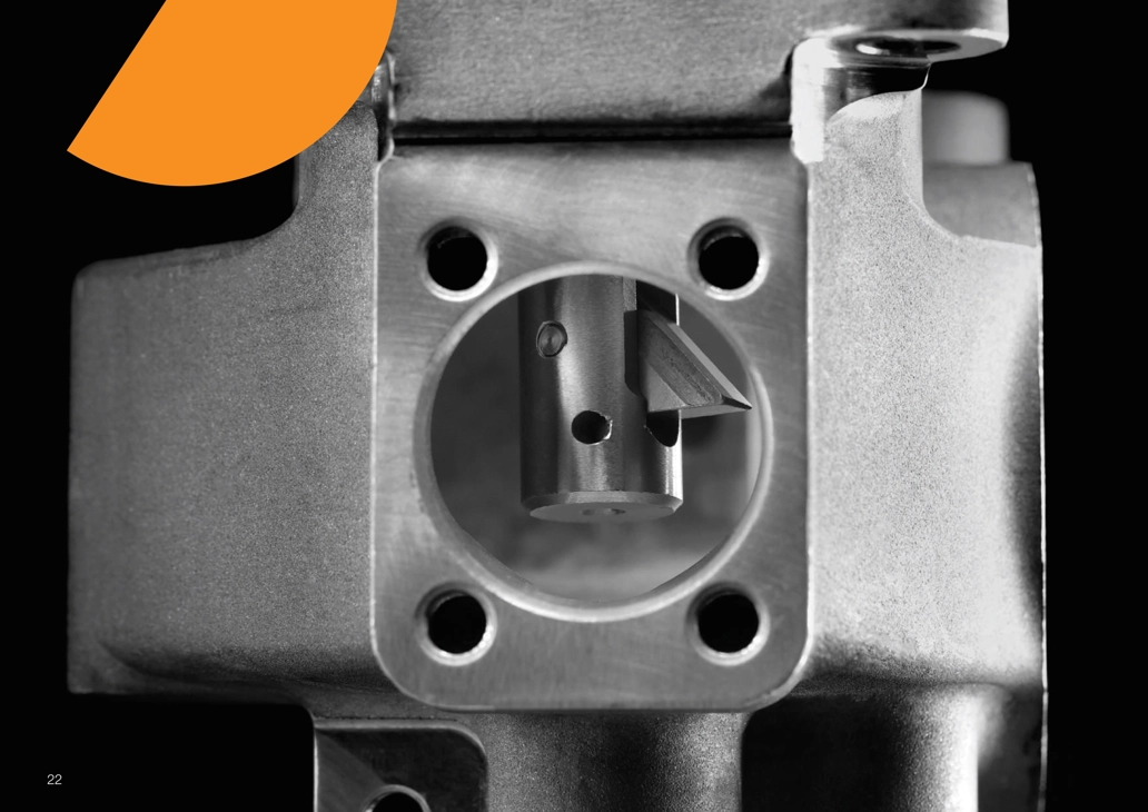
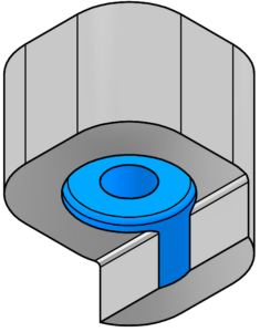
How does the UBackTool works?
- The UBack tool-holders are designed for CNC automated operations and are compatible with USPOT inserts for back counterboring and spot-facing, as well as UCHAMF inserts for back countersinking.
- The insert’s opening and closing hydraulic mechanism is activated by directing coolant through the spindle and tool-holder. This system supports coolant, emulsion, or air with a minimum pump pressure of 6 bar (90 PSI).
- The tool-holder is specifically engineered to prevent scratches while passing through the pilot hole.
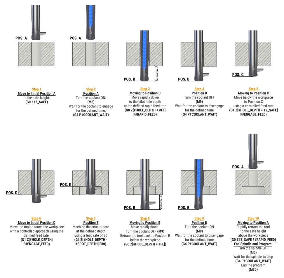
UBack Programming guidelines - Continuous Cut
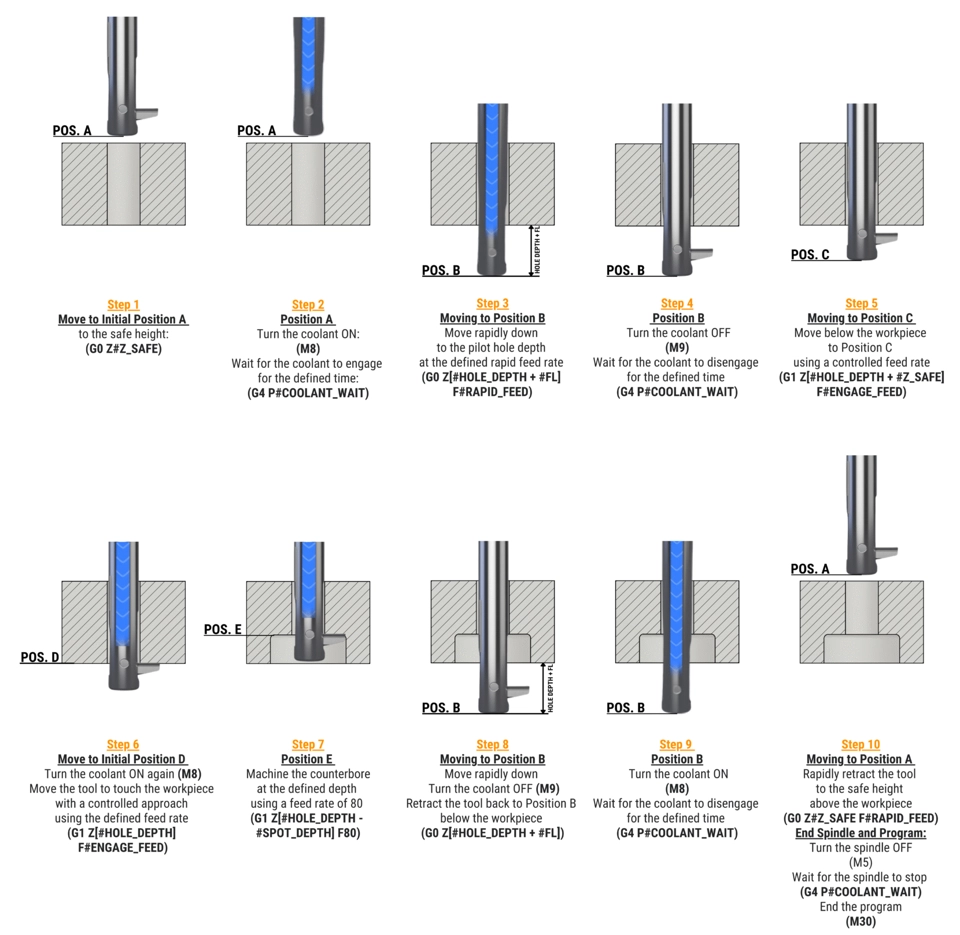
- (1) The Folding Length (FL) parameter is listed in the tool-holder tables and is the same for both USPOT inserts and UCHAMF inserts.
- (2) The illustrated operation sequence above demonstrates working with a USPOT insert but remains the same when using a UCHAMF insert.
UBack Programming guidelines – Interrupted Cut
For interrupted cuts:
Step 6–7 → Perform without internal coolant
Use external coolant only (also refer below “Counterbore Machining Guidelines for Specific Conditions”)

(1) The Folding Length (FL) parameter is listed in the tool-holder tables and is the same for both USPOT inserts and UCHAMF inserts.
(2) The illustrated operation sequence above demonstrates working with a USPOT insert but remains the same when using a UCHAMF insert.
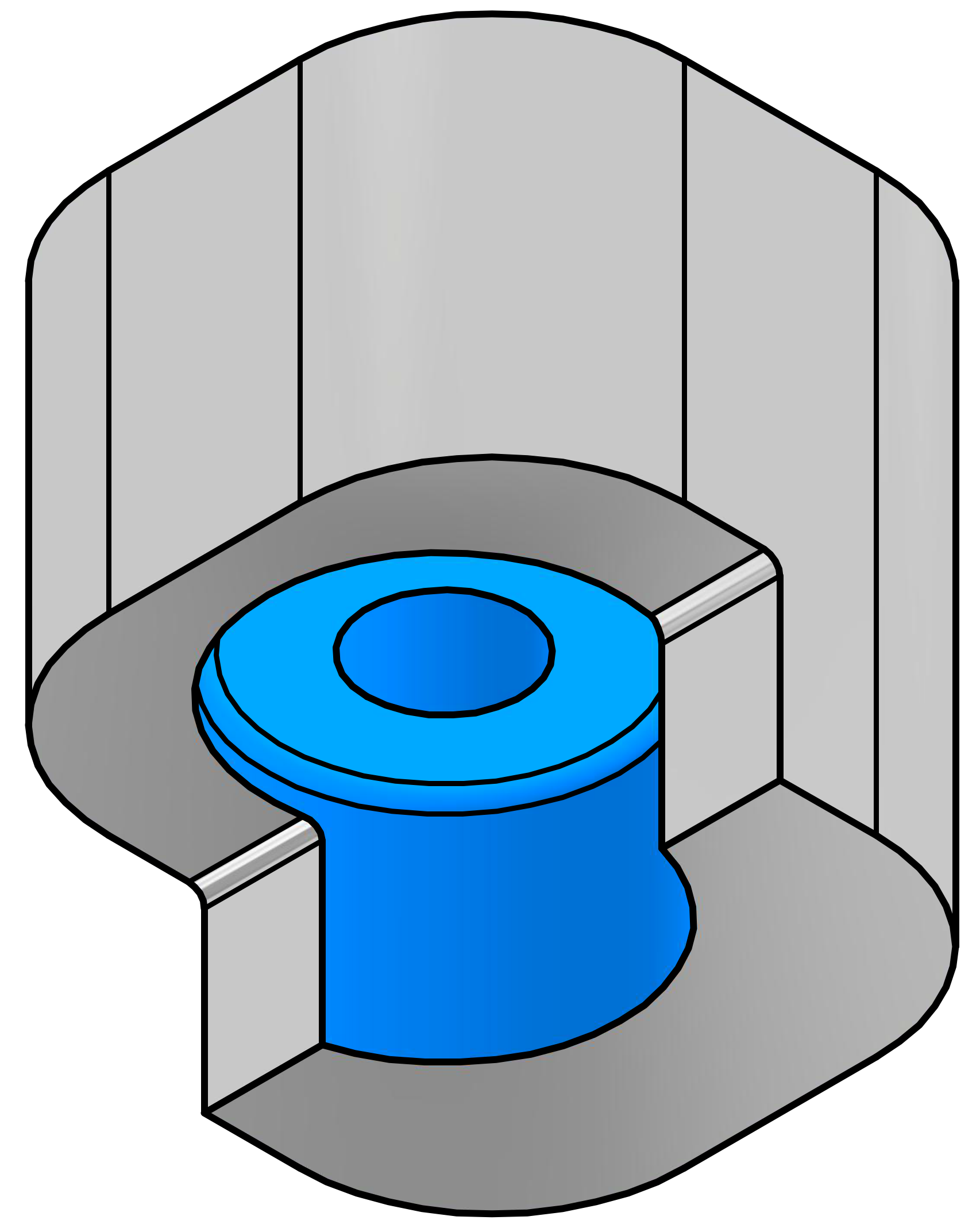
Counterbore Machining Guidelines for Specific Conditions
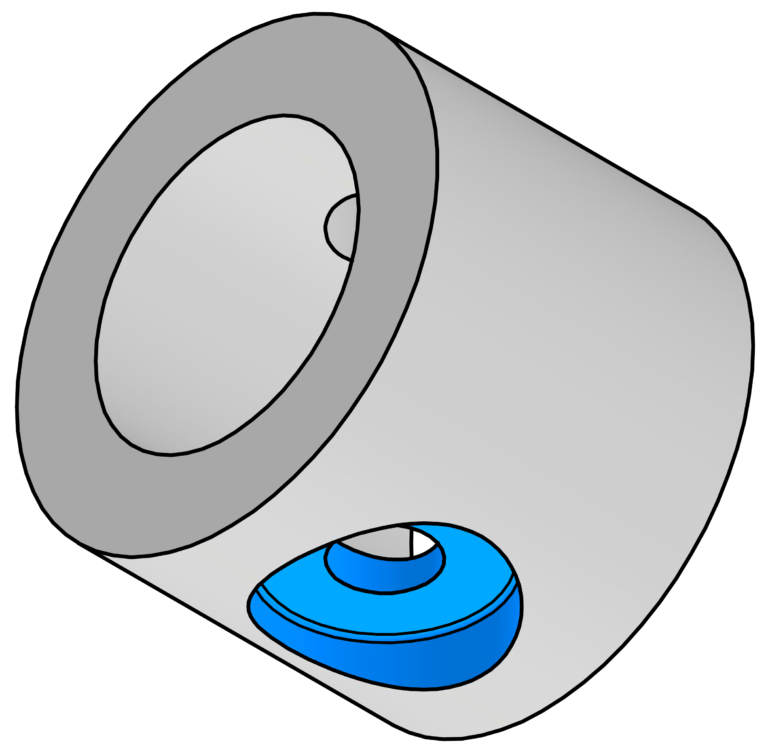
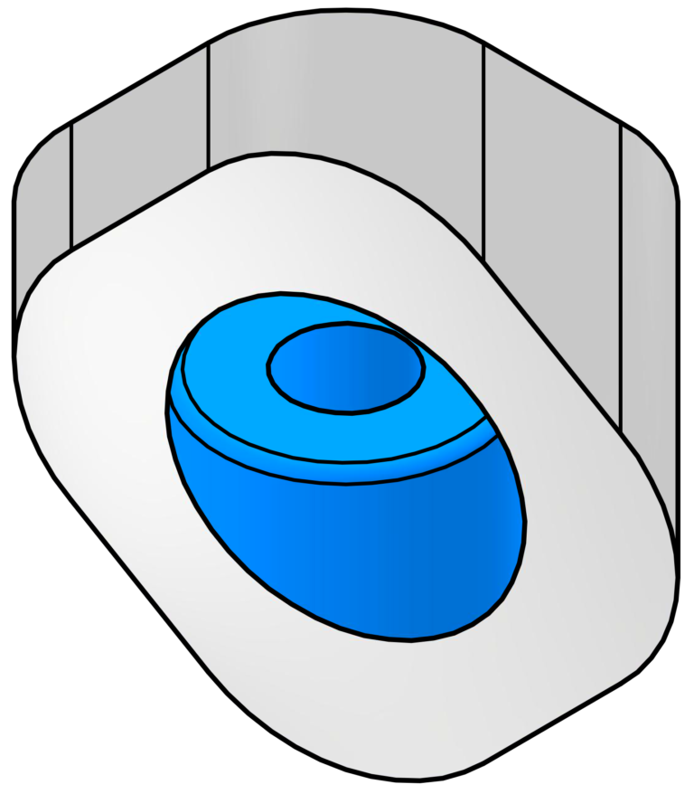
Counterbore on Cylindrical Bore
- Use with Internal Coolant
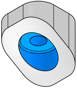
Counterbore on Sloped Surface
- Use external coolant only
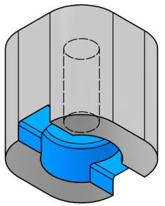
Counterbore on Slot
- Fully Interrupted Cut
- Use external coolant only
- Consider reduced stability and adjust cutting parameters by reducing them by 30%
Counterbore on Shoulder
- Fully Interrupted Cut
- Use external coolant only
- Consider reduced stability and adjust cutting parameters by reducing them by 30%
Counterbore on Shoulder
- Fully Interrupted Cut
- Use external coolant only
- Consider reduced stability and adjust cutting parameters by reducing them by 30%
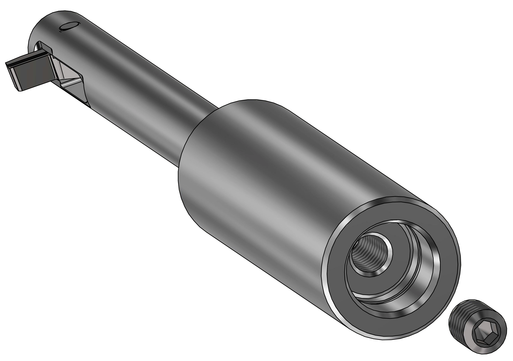
UBack Tool Insert Replacement
- UBack inserts can be easily replaced using just a pin and a screw, without the need for any additional mounting devices.
- The pin is used to secure the insert within the tool-holder, preventing it from retracting while unscrewing.
- The UBack spare parts, including the screw, key, and pin, are standardized across the entire UBack tool-holder range.
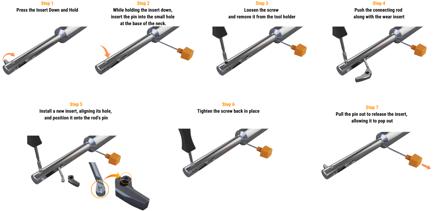
NOTE: The illustrated insert replacement above is demonstrated with a USPOT insert but remains the same when using a UCHAMF insert.
Configuring UBACK tool-holders for different cooling systems
UBACK tool-holders are designed for controlling insert retraction using emulsion, air, or Minimum Quantity Lubrication (MQL) coolant systems. When using air or MQL, seal the tool-holder’s coolant inlet with the supplied plug set screw.
UBack Cutting Recommendations
The table below presents cutting recommendations, outlining initial feed rates and cutting speed for materials group based on ISO 513 and VDI 3323 standards.
(1) To ensure optimal performance and tool-life under varying conditions:
- For moderate tool-holder or workpiece stability, consider reducing feed rates by up to 10%.
- For poor tool-holder or workpiece stability, it’s advisable to decrease feed rates by up to 30%.
Additionally, the operator must ensure the utilization of appropriate coolant media directed to the cutting tip of the blade and right-hand machining (clockwise).
ISO | Material | Condition | As is | DIN W.-Nr. | vc(1) cutting speed | Series B | Series C | Series D | Series E | Series F | Series G | Recommended | Coolant | ||
P | Non-alloy steel | <0.25% C | Annealed | 1020 | 1.0044 | 60-120 | 0.03 | 0.04 | 0.05 | 0.07 | 0.08 | 0.09 | PL ML | Air / Wet | |
≥0.25% C | Annealed | 1035 | 1.0501 | ||||||||||||
<0.55% C | Quenched and tempered | 1045 | 1.1201 | ||||||||||||
≥0.55% C | Annealed | 1055 | 1.0535 | ||||||||||||
Quenched and tempered | 1060 | 1.1221 | |||||||||||||
Low alloy | Annealed | G92600 | 1.5028 | 50-120 | 0.03 | 0.04 | 0.05 | 0.07 | 0.08 | 0.09 | |||||
Quenched and tempered | 4130 | 1.7218 | |||||||||||||
4142 | 1.2332 | ||||||||||||||
5045 | 1.7006 | 50-100 | |||||||||||||
High alloyed steel, | Annealed | H13 | 1.2344 | 40-90 | 0.02 | 0.03 | 0.04 | 0.05 | 0.06 | 0.08 | |||||
Quenched and tempered | M33 | 1.3249 | |||||||||||||
Stainless steel and cast | Ferritic/martensitic | 420 | 1.4021 | ||||||||||||
Martensitic | |||||||||||||||
M | Stainless steel | Austenitic, duplex | 304L | 1.4306 | 50-100 | 0.03 | 0.04 | 0.05 | 0.07 | 0.08 | 0.09 | PL | Wet | ||
K | Gray cast iron (GG) | Ferritic / pearlitic | Class 25 | 0.6015 | 60-120 | 0.03 | 0.04 | 0.05 | 0.07 | 0.08 | 0.09 | PL | Air / Wet | ||
Pearlitic / martensitic | Grade H20 | 36037 | |||||||||||||
Nodular cast iron (GGG) | Ferritic | 60-40-18 | 0.7043 | 50-100 | 0.02 | 0.03 | 0.04 | 0.05 | 0.06 | 0.08 | |||||
Pearlitic | F33500 | 0.705 | |||||||||||||
Malleable cast iron | Ferritic | A47 | 0.8135 | ||||||||||||
Pearlitic | A220 Class | 0.8155 | |||||||||||||
N | Aluminum-wrought alloys | Not hardenable | 5005 | 3.3315 | 100-160 | 0.05 | 0.06 | 0.08 | 0.10 | 0.12 | 0.14 | PL | Wet | ||
Hardenable | 7075 | 3.4365 | |||||||||||||
Aluminum-cast alloys | ≤12% Si | Not hardenable | 518 | 3.3292 | |||||||||||
Hardenable | 515 | 3.3241 | |||||||||||||
>12% Si | High temperature | 390 |
| ||||||||||||
Copper alloys | >1% Pb | Free cutting | C36000 | 2.0375 | 90-130 | ||||||||||
| Brass | C22000 | 2.023 | ||||||||||||
Electrolytic copper | C63000 | 2.0966 | |||||||||||||
Non metallic | Duroplastics, fiber | Bakelite |
| 180-305 | |||||||||||
Hard rubber | Ebonite |
| |||||||||||||
S | High temperature alloys | Fe based | Annealed | 330 | 1.4864 | 40-80 | 0.02 | 0.03 | 0.04 | 0.05 | 0.06 | 0.08 | PL ML | Wet | |
Hardened | S590 | 1.4977 | |||||||||||||
Ni or Co based | Annealed | Incoloy 825 | 2.4858 | 25-40 | |||||||||||
Hardened | Inconel 718 | 2.4668 | |||||||||||||
Cast | Nimocast K24 | 2.4674 | |||||||||||||
Titanium alloys | Pure | Titanium G.1 | 3.7024 | 30-60 | 0.02 | 0.03 | 0.04 | 0.05 | 0.06 | 0.08 | |||||
Alpha+beta alloys, | Titanium G.5 | 3.7165 | |||||||||||||
H | Hardened steel | Hardened | HARDOX 500 |
| 30-50 | 0.02 | 0.02 | 0.03 | 0.04 | 0.05 | 0.06 | ML HL | Air | ||
Hardened | HARDOX Extreme |
| 30-40 | ||||||||||||
Chilled cast iron | Cast | A532 lllA 25% Cr | 0.965 | 45-50 | 0.02 | 0.02 | 0.03 | 0.04 | 0.05 | 0.06 | |||||
Cast iron | Hardened | A532 IID 20% CrMo | 0.9645 | 30-50 | 0.02 | 0.02 | 0.03 | 0.04 | 0.05 | 0.06 | |||||
(1) To ensure optimal performance and tool-life under varying conditions:
- For moderate tool-holder or workpiece stability, consider reducing feed rates by up to 10%.
- For poor tool-holder or workpiece stability, it’s advisable to decrease feed rates by up to 30%.
- When using UCHAMF inserts reduce all cutting recommendations by 20%
Available Coating types and surface treatments:
NOGA’s Code | Coating | Key Features | Applications | Industries | Material Examples | ISO GROUP | |||||
P | M | K | N | S | H | ||||||
NCT | TiAlN | Excellent thermal | High-speed cutting and | Aerospace, Automotive, General Engineering | AISI 304, 42CrMo4, | ✓ | ✓ | ✓ | X | ✓ | ✓ |
NCD | TiAlSiN | Very high hardness, Suitable for hardened | High-performance | Aerospace, Automotive, Die & Mold | Inconel 718, AISI | ✓ | ✓ | X | X | ✓ | ✓ |
NCA | AlTiSiN | High hardness, thermal Works well in dry, Suitable for hardened | High-speed machining | Aerospace, Automotive, Precision Engineering | AISI 316, AISI H13, | ✓ | ✓ | X | X | ✓ | ✓ |
NCN | AlCrN | High oxidation | General machining in | Automotive, Aerospace, Die & Mold | AISI 304, AISI 1045, | ✓ | ✓ | ✓ | ✓ | X | X |
NCW | AlTiN | High hardness, wear | Heavy-duty machining Dry & abrasive | Aerospace, Automotive, Heavy Engineering | AISI 4340, M2 HSS, | ✓ | ✓ | ✓ | X | ✓ | X |
NCB | TiB₂ | Excellent thermal Prevents material | High-speed machining | Aerospace, Automotive, | AL7075, 6061-T6, | X | X | X | ✓ | ✓ | X |
POL | Polishing (Surface | Removes scratches, micro-defects. Produces smooth finish and reduces friction. | High-speed finishing | Aerospace, Automotive | AL7075, 6061-T6, | X | X | X | ✓ | X | X |
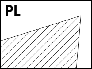
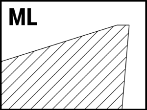
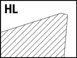
Chip-formers:
PL
Positive cutting land
Suitable for all around purpose
and ISO P,M,K,N,S as well as composite materials
ML
Moderate cutting land
Suitable for and ISO P,M,K,S,H
Materials
HL
Negative cutting land
Suitable for and ISO P,M,K,S,H
Materials
👨🔧 USPOT Configurator
Insert & Tool-Holder Code Generator
👨🔧 UCHAMF Configurator
Insert & Tool-Holder Code Generator