
UBURR® CNC Hole Deburring Tool for Front & Back Edges
Deburr both sides of a drilled through-hole in one machining cycle. UBURR combines a spring-controlled replaceable blade with the NOGA MT DURASHIELD tool-holder for fast, repeatable front-and-back hole deburring.
Automatic Front-and-Back Deburring for Drilled Through-Holes
UBURR is a CNC hole deburring tool designed to remove burrs from both the front and back edges of a drilled through-hole. The spring-loaded cutting blade retracts while passing through the pilot hole and extends again after exit, allowing the return stroke to deburr the rear edge. This eliminates the need to flip the workpiece or use a second deburring setup.
How the UBURR Deburring Cycle Works
The spring mechanism automatically controls blade extension and retraction during the cycle.
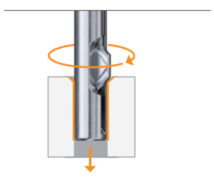
Deburr the Front Edge
The extended blade engages the front hole edge and removes the burr during entry.
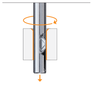
Blade Retracts Through the Bore
Feed pressure overcomes the spring force and retracts the blade while it passes through the pilot hole.
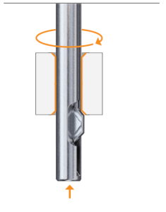
Deburr the Back Edge
After exiting the bore, the spring extends the blade again so the return stroke finishes the rear edge.
See UBURR in Action
Use the videos below to see the UBURR mechanism and machining concept in real applications. YouTube videos autoplay muted and loop continuously.
UBURR in Action — Front & Back Deburring
See UBURR operating on a real machined component and demonstrating the automatic two-sided deburring concept.
UBURR Demonstration Video
Watch a UBURR machining demonstration on YouTube to see the deburring concept and the tool family in practical use.
UBURR Short Demo
Short-form UBURR video preview for quick viewing of the tool in action and the deburring concept.
UBURR Machining Demo
Additional UBURR machining demonstration showing the tool and automatic deburring process in action.
YouTube videos autoplay muted and loop continuously. Instagram playback remains platform-controlled.
Choose the Right UBURR Blade Geometry
UBURR combines a unique spherical cutting-edge surface with different cutting-land geometries. Select the land geometry according to material group, edge strength requirement and application severity.

The rounded cutting-edge surface is engineered to allow the blade to retract through the pilot hole while minimizing marking of the internal bore surface.
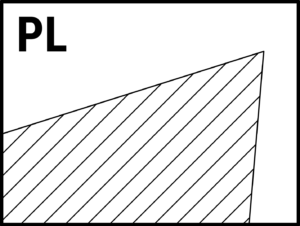
PL
RECOMMENDED STARTPositive cutting land for broad, general-purpose UBURR applications. This is the preferred starting geometry when no special edge-strength requirement exists.
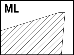
ML
STRONGER EDGEModerate cutting land with a stronger cutting edge for more demanding conditions and materials where added edge support is beneficial.
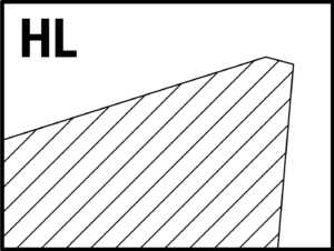
HL
SPECIALSpecial high-land geometry intended for selected hardened-material applications. HL is not part of the standard blade table shown below.
Select the Correct UBURR Blade
Use the full UBURR blade selector below. Enter the pilot-hole diameter to show the compatible blade size, then search or filter by blade material, coating and cutting-edge geometry. The selector preserves the current blade SKUs, designations and descriptions supplied in the blade table.
Blade Finder
Enter the pilot-hole diameter to identify the compatible blade size, or search and filter the complete blade range by material, coating and cutting-edge geometry.
2.5
Ø2.5 (0.098") ≤ d < Ø3.0 (0.118")
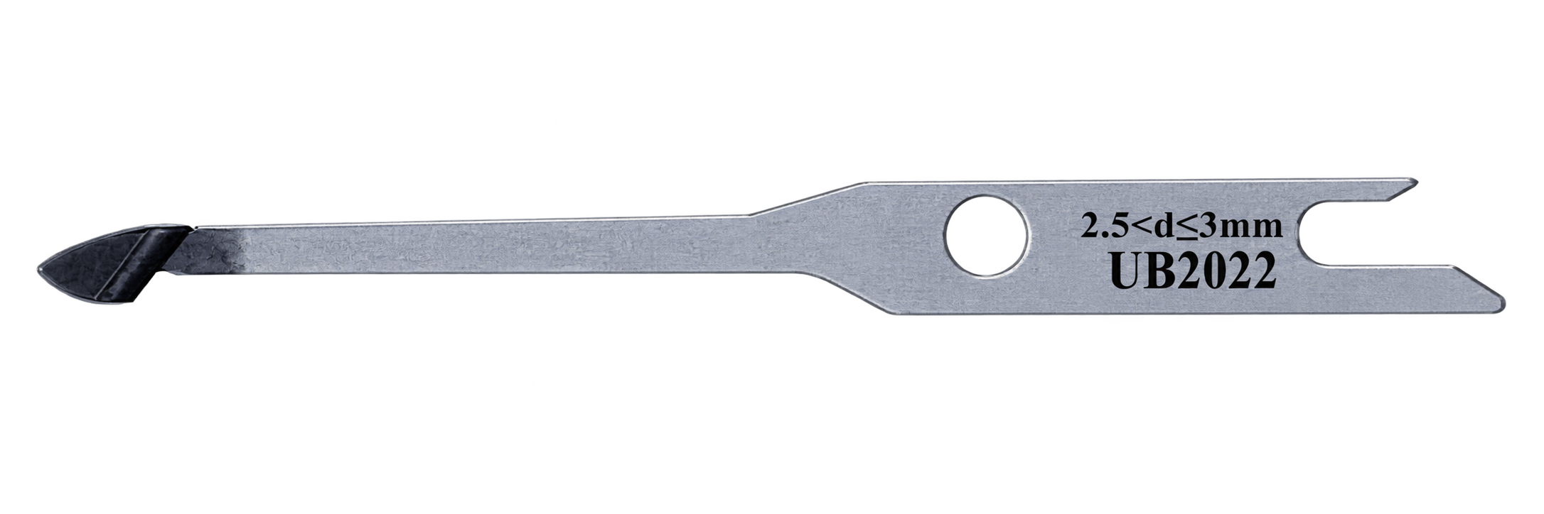
| Blade SKU | Designation | Blade Material | Coating / Chip-former | Description |
|---|---|---|---|---|
| NEWUB2020(1) | UB-TSB-2.5-PL | HSS | Uncoated PL geometry | HSS Blade size 2.5 without coating and PL (Positive Land) cutting-edge geometry |
| NEWUB2021(1) | UB-TSB-2.5-PL-NCW | HSS | AlTiN PL geometry | HSS blade size 2.5 with AlTiN coating and PL (Positive Land) cutting-edge geometry |
| NEWUB2022(1) | UB-TSB-2.5-PL-NCT | HSS | TiAlN PL geometry | HSS Blade size 2.5 with TiAlN coating and PL (Positive Land) cutting-edge geometry |
3
Ø3.0 (0.118") ≤ d < Ø5.0 (0.197")
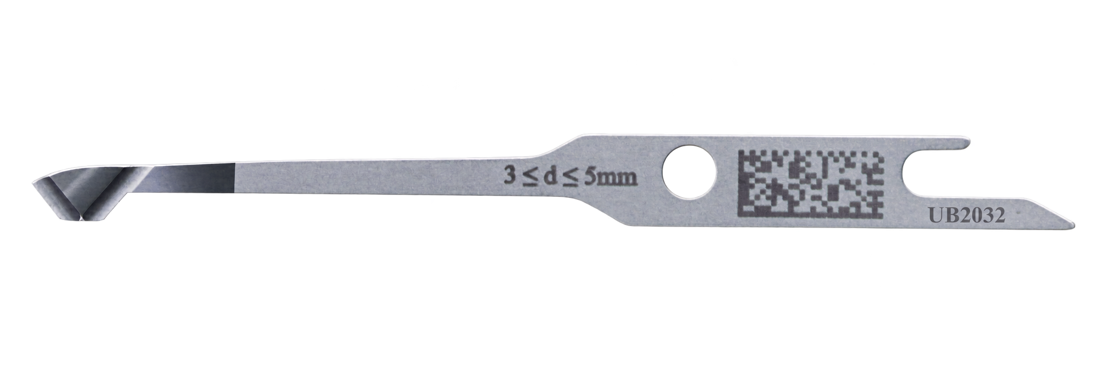
| Blade SKU | Designation | Blade Material | Coating / Chip-former | Description |
|---|---|---|---|---|
| UB2030 | UB-TSB-3-PL | HSS | Uncoated PL geometry | HSS blade size 3 without coating and PL (Positive Land) cutting-edge geometry |
| NEWUB2031 | UB-TSB-3-PL-NCW | HSS | AlTiN PL geometry | HSS blade size 3 with AlTiN coating and PL (Positive Land) cutting-edge geometry |
| UB2032 | UB-TSB-3-PL-NCT | HSS | TiAlN PL geometry | HSS blade size 3 with TiAlN coating and PL (Positive Land) cutting-edge geometry |
| NEWUB2034 | UB-TSB-3-ML-NCT | HSS | TiAlN ML geometry | HSS blade size 3 with TiAlN coating and ML (Moderate Land) cutting-edge geometry |
| NEWUB2036 | UB-SCB-3-PL-NCT | Carbide | TiAlN PL geometry | Carbide blade size 3 with TiAlN coating and PL (Positive Land) cutting-edge geometry |
| NEWUB2038 | UB-SCB-3-ML-NCT | Carbide | TiAlN ML geometry | Carbide blade size 3 with TiAlN coating and ML (Moderate Land) cutting-edge geometry |
5
d ≥ Ø5.0 (0.197")
| Blade SKU | Designation | Blade Material | Coating / Chip-former | Description |
|---|---|---|---|---|
| UB2060 | UB-TSB-5-PL | HSS | Uncoated PL geometry | HSS blade size 5 without coating and PL (Positive Land) cutting-edge geometry |
| NEWUB2061 | UB-TSB-5-PL-NCW | HSS | AlTiN PL geometry | HSS blade size 5 with AlTiN coating and PL (Positive Land) cutting-edge geometry |
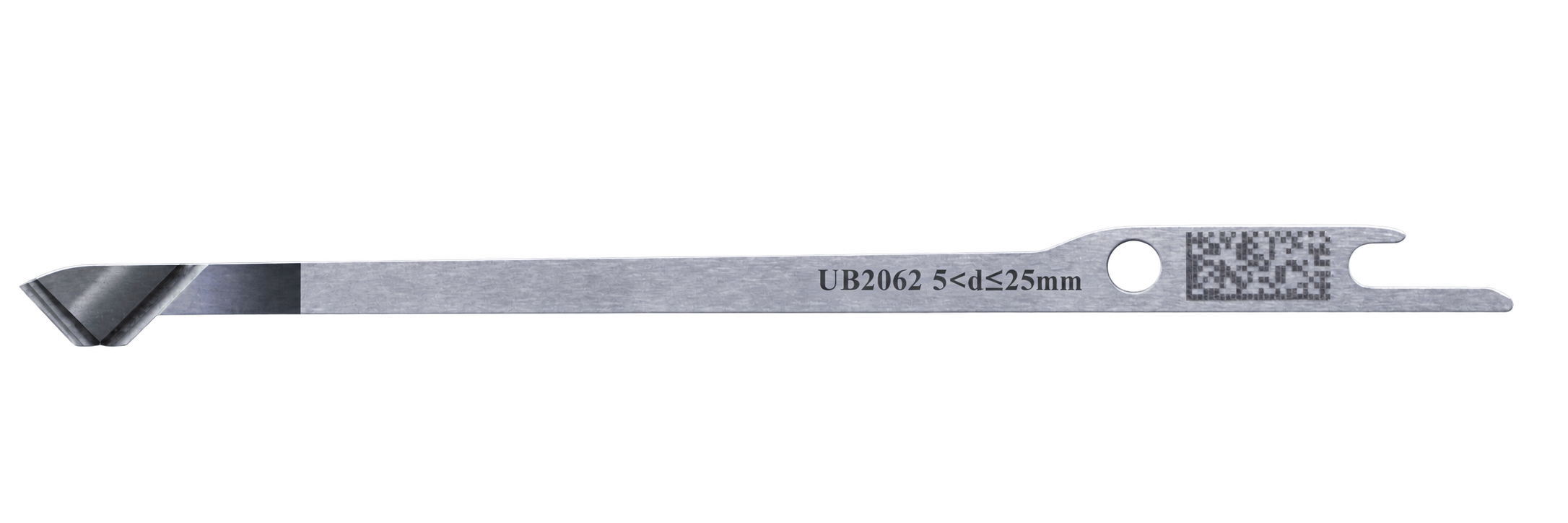
| UB2062 | UB-TSB-5-PL-NCT | HSS | TiAlN PL geometry | HSS blade size 5 with TiAlN coating and PL (Positive Land) cutting-edge geometry |
| NEWUB2063 | UB-TSB-5-ML-NCT | HSS | TiAlN ML geometry | HSS blade size 5 with TiAlN coating and ML (Moderate Land) cutting-edge geometry |
| NEWUB2067 | UB-SCB-5-PL-NCT | Carbide | TiAlN PL geometry | Carbide blade size 5 with TiAlN coating and PL (Positive Land) cutting-edge geometry |
| NEWUB2069 | UB-SCB-5-ML-NCT | Carbide | TiAlN ML geometry | Carbide blade size 5 with TiAlN coating and ML (Moderate Land) cutting-edge geometry |
Blade images: transparent PNGs are loaded directly from the NOGA WordPress Media Library.
Polished / Uncoated HSS
Useful for general cutting and applications where a sharp uncoated cutting edge is preferred.
TiAlN Coating
High thermal stability and wear resistance for general-purpose and higher-speed machining in wet or dry conditions.
AlTiN Coating
High hardness and thermal stability for demanding cutting conditions and abrasive applications.
UBURR Blade Coating Selection Guide
Comparison of available coating codes, key characteristics, typical applications and ISO material-group suitability.
| NOGA's Code | Coating | Key Features | Applications | Industries | Material Examples | ISO GROUP | |||||
|---|---|---|---|---|---|---|---|---|---|---|---|
| P | M | K | N | S | H | ||||||
| NCT | TiAlN | Excellent thermal stability, oxidation resistance, and wear resistance. | High-speed cutting and general-purpose machining. | Aerospace, Automotive, General Engineering. | AISI 304, 42CrMo4, Grey Cast Iron (GG), Ti6Al4V | ✓ | ✓ | ✓ | × | ✓ | ✓ |
| NCW | AlTiN | High hardness, wear resistance, thermal stability up to 1100°C. | Heavy-duty machining and high-speed cutting. | Aerospace, Foundries, Heavy Engineering. | AISI 4340, M2 HSS, Grey Cast Iron (GG) | ✓ | ✓ | ✓ | × | ✓ | × |
Find the Correct UBURR Holder
Enter the actual pilot-hole diameter to identify the corresponding standard holder and set. The standard nominal series runs from Ø2.5 to Ø25.0 mm in 0.5 mm increments.


| Holder SKU | Holder Designation | Set SKU | Pilot-Hole Range | Standard Blade | Blade Size | Shank Ø DS | LTB1 | LTB2 | H | L |
|---|---|---|---|---|---|---|---|---|---|---|
| UB1025 | UB-d025-C08-H29-L69 | UB2500 | 2.50–3.00 0.098–0.118″ |
UB2020¹ | 2.5¹ | 8 mm 0.315″ |
N/A | 7 | 29 mm 1.142″ |
69 mm 2.717″ |
| UB1030 | UB-d030-C08-H29-L85 | UB3000 | 3.00–3.50 0.118–0.138″ |
UB2030 | 3 | 8 mm 0.315″ |
4 | 10 | 29 mm 1.142″ |
85 mm 3.346″ |
| UB1035 | UB-d035-C08-H29-L85 | UB3001 | 3.50–4.00 0.138–0.157″ |
UB2030 | 3 | 8 mm 0.315″ |
4 | 10 | 29 mm 1.142″ |
85 mm 3.346″ |
| UB1040 | UB-d040-C08-H29-L85 | UB3002 | 4.00–4.50 0.157–0.177″ |
UB2030 | 3 | 8 mm 0.315″ |
4 | 10 | 29 mm 1.142″ |
85 mm 3.346″ |
| UB1045 | UB-d045-C08-H29-L85 | UB3003 | 4.50–5.00 0.177–0.197″ |
UB2030 | 3 | 8 mm 0.315″ |
4 | 10 | 29 mm 1.142″ |
85 mm 3.346″ |
| UB1050 | UB-d050-C08-H53-L115 | UB3004 | 5.00–5.50 0.197–0.217″ |
UB2060 | 5 | 8 mm 0.315″ |
4 | 12 | 53 mm 2.087″ |
115 mm 4.528″ |
| UB1055 | UB-d055-C08-H53-L115 | UB3005 | 5.50–6.00 0.217–0.236″ |
UB2060 | 5 | 8 mm 0.315″ |
4 | 12 | 53 mm 2.087″ |
115 mm 4.528″ |
| UB1060 | UB-d060-C08-H53-L115 | UB3006 | 6.00–6.50 0.236–0.256″ |
UB2060 | 5 | 8 mm 0.315″ |
4 | 12 | 53 mm 2.087″ |
115 mm 4.528″ |
| UB1065 | UB-d065-C08-H53-L115 | UB3007 | 6.50–7.00 0.256–0.276″ |
UB2060 | 5 | 8 mm 0.315″ |
4 | 12 | 53 mm 2.087″ |
115 mm 4.528″ |
| UB1070 | UB-d070-C08-H53-L115 | UB3008 | 7.00–7.50 0.276–0.295″ |
UB2060 | 5 | 8 mm 0.315″ |
4 | 12 | 53 mm 2.087″ |
115 mm 4.528″ |
| UB1075 | UB-d075-C08-H53-L115 | UB3009 | 7.50–8.00 0.295–0.315″ |
UB2060 | 5 | 8 mm 0.315″ |
4 | 12 | 53 mm 2.087″ |
115 mm 4.528″ |
| UB1080 | UB-d080-C10-H53-L115 | UB3010 | 8.00–8.50 0.315–0.335″ |
UB2060 | 5 | 10 mm 0.394″ |
4 | 12 | 53 mm 2.087″ |
115 mm 4.528″ |
| UB1085 | UB-d085-C10-H53-L115 | UB3011 | 8.50–9.00 0.335–0.354″ |
UB2060 | 5 | 10 mm 0.394″ |
4 | 12 | 53 mm 2.087″ |
115 mm 4.528″ |
| UB1090 | UB-d090-C10-H53-L115 | UB3012 | 9.00–9.50 0.354–0.374″ |
UB2060 | 5 | 10 mm 0.394″ |
4 | 12 | 53 mm 2.087″ |
115 mm 4.528″ |
| UB1095 | UB-d095-C10-H53-L115 | UB3013 | 9.50–10.00 0.374–0.394″ |
UB2060 | 5 | 10 mm 0.394″ |
4 | 12 | 53 mm 2.087″ |
115 mm 4.528″ |
| UB1100 | UB-d100-C10-H80-L125 | UB3014 | 10.00–10.50 0.394–0.413″ |
UB2060 | 5 | 10 mm 0.394″ |
4 | 12 | 80 mm 3.150″ |
125 mm 4.921″ |
| UB1105 | UB-d105-C10-H80-L125 | UB3015 | 10.50–11.00 0.413–0.433″ |
UB2060 | 5 | 10 mm 0.394″ |
4 | 12 | 80 mm 3.150″ |
125 mm 4.921″ |
| UB1110 | UB-d110-C10-H80-L125 | UB3016 | 11.00–11.50 0.433–0.453″ |
UB2060 | 5 | 10 mm 0.394″ |
4 | 12 | 80 mm 3.150″ |
125 mm 4.921″ |
| UB1115 | UB-d115-C12-H80-L125 | UB3017 | 11.50–12.00 0.453–0.472″ |
UB2060 | 5 | 12 mm 0.472″ |
4 | 12 | 80 mm 3.150″ |
125 mm 4.921″ |
| UB1120 | UB-d120-C12-H80-L125 | UB3018 | 12.00–12.50 0.472–0.492″ |
UB2060 | 5 | 12 mm 0.472″ |
4 | 12 | 80 mm 3.150″ |
125 mm 4.921″ |
| UB1125 | UB-d125-C12-H80-L125 | UB3019 | 12.50–13.00 0.492–0.512″ |
UB2060 | 5 | 12 mm 0.472″ |
4 | 12 | 80 mm 3.150″ |
125 mm 4.921″ |
| UB1130 | UB-d130-C12-H80-L125 | UB3020 | 13.00–13.50 0.512–0.531″ |
UB2060 | 5 | 12 mm 0.472″ |
4 | 12 | 80 mm 3.150″ |
125 mm 4.921″ |
| UB1135 | UB-d135-C12-H80-L125 | UB3021 | 13.50–14.00 0.531–0.551″ |
UB2060 | 5 | 12 mm 0.472″ |
4 | 12 | 80 mm 3.150″ |
125 mm 4.921″ |
| UB1140 | UB-d140-C12-H80-L125 | UB3022 | 14.00–14.50 0.551–0.571″ |
UB2060 | 5 | 12 mm 0.472″ |
4 | 12 | 80 mm 3.150″ |
125 mm 4.921″ |
| UB1145 | UB-d145-C12-H80-L125 | UB3023 | 14.50–15.00 0.571–0.591″ |
UB2060 | 5 | 12 mm 0.472″ |
4 | 12 | 80 mm 3.150″ |
125 mm 4.921″ |
| UB1150 | UB-d150-C12-H80-L125 | UB3024 | 15.00–15.50 0.591–0.610″ |
UB2060 | 5 | 12 mm 0.472″ |
4 | 12 | 80 mm 3.150″ |
125 mm 4.921″ |
| UB1155 | UB-d155-C12-H80-L125 | UB3025 | 15.50–16.00 0.610–0.630″ |
UB2060 | 5 | 12 mm 0.472″ |
4 | 12 | 80 mm 3.150″ |
125 mm 4.921″ |
| UB1160 | UB-d160-C16-H80-L125 | UB3026 | 16.00–16.50 0.630–0.650″ |
UB2060 | 5 | 16 mm 0.630″ |
4 | 12 | 80 mm 3.150″ |
125 mm 4.921″ |
| UB1165 | UB-d165-C16-H80-L125 | UB3027 | 16.50–17.00 0.650–0.669″ |
UB2060 | 5 | 16 mm 0.630″ |
4 | 12 | 80 mm 3.150″ |
125 mm 4.921″ |
| UB1170 | UB-d170-C16-H80-L125 | UB3028 | 17.00–17.50 0.669–0.689″ |
UB2060 | 5 | 16 mm 0.630″ |
4 | 12 | 80 mm 3.150″ |
125 mm 4.921″ |
| UB1175 | UB-d175-C16-H80-L125 | UB3029 | 17.50–18.00 0.689–0.709″ |
UB2060 | 5 | 16 mm 0.630″ |
4 | 12 | 80 mm 3.150″ |
125 mm 4.921″ |
| UB1180 | UB-d180-C16-H80-L125 | UB3030 | 18.00–18.50 0.709–0.728″ |
UB2060 | 5 | 16 mm 0.630″ |
4 | 12 | 80 mm 3.150″ |
125 mm 4.921″ |
| UB1185 | UB-d185-C16-H80-L125 | UB3031 | 18.50–19.00 0.728–0.748″ |
UB2060 | 5 | 16 mm 0.630″ |
4 | 12 | 80 mm 3.150″ |
125 mm 4.921″ |
| UB1190 | UB-d190-C16-H80-L125 | UB3032 | 19.00–19.50 0.748–0.768″ |
UB2060 | 5 | 16 mm 0.630″ |
4 | 12 | 80 mm 3.150″ |
125 mm 4.921″ |
| UB1195 | UB-d195-C20-H80-L125 | UB3033 | 19.50–20.00 0.768–0.787″ |
UB2060 | 5 | 20 mm 0.787″ |
4 | 12 | 80 mm 3.150″ |
125 mm 4.921″ |
| UB1200 | UB-d200-C20-H80-L125 | UB3034 | 20.00–20.50 0.787–0.807″ |
UB2060 | 5 | 20 mm 0.787″ |
4 | 12 | 80 mm 3.150″ |
125 mm 4.921″ |
| UB1205 | UB-d205-C20-H80-L125 | UB3035 | 20.50–21.00 0.807–0.827″ |
UB2060 | 5 | 20 mm 0.787″ |
4 | 12 | 80 mm 3.150″ |
125 mm 4.921″ |
| UB1210 | UB-d210-C20-H80-L125 | UB3036 | 21.00–21.50 0.827–0.846″ |
UB2060 | 5 | 20 mm 0.787″ |
4 | 12 | 80 mm 3.150″ |
125 mm 4.921″ |
| UB1215 | UB-d215-C20-H80-L125 | UB3037 | 21.50–22.00 0.846–0.866″ |
UB2060 | 5 | 20 mm 0.787″ |
4 | 12 | 80 mm 3.150″ |
125 mm 4.921″ |
| UB1220 | UB-d220-C20-H80-L125 | UB3038 | 22.00–22.50 0.866–0.886″ |
UB2060 | 5 | 20 mm 0.787″ |
4 | 12 | 80 mm 3.150″ |
125 mm 4.921″ |
| UB1225 | UB-d225-C20-H80-L125 | UB3039 | 22.50–23.00 0.886–0.906″ |
UB2060 | 5 | 20 mm 0.787″ |
4 | 12 | 80 mm 3.150″ |
125 mm 4.921″ |
| UB1230 | UB-d230-C20-H80-L125 | UB3040 | 23.00–23.50 0.906–0.925″ |
UB2060 | 5 | 20 mm 0.787″ |
4 | 12 | 80 mm 3.150″ |
125 mm 4.921″ |
| UB1235 | UB-d235-C20-H80-L125 | UB3041 | 23.50–24.00 0.925–0.945″ |
UB2060 | 5 | 20 mm 0.787″ |
4 | 12 | 80 mm 3.150″ |
125 mm 4.921″ |
| UB1240 | UB-d240-C20-H80-L125 | UB3042 | 24.00–24.50 0.945–0.965″ |
UB2060 | 5 | 20 mm 0.787″ |
4 | 12 | 80 mm 3.150″ |
125 mm 4.921″ |
| UB1245 | UB-d245-C20-H80-L125 | UB3043 | 24.50–25.00 0.965–0.984″ |
UB2060 | 5 | 20 mm 0.787″ |
4 | 12 | 80 mm 3.150″ |
125 mm 4.921″ |
| UB1250 | UB-d250-C20-H80-L125 | UB3044 | 25.00–25.50 0.984–1.004″ |
UB2060 | 5 | 20 mm 0.787″ |
4 | 12 | 80 mm 3.150″ |
125 mm 4.921″ |
Condensed selection table for faster product choice. For complete machining recommendations, thread pre-drill reference, programming limits and cutting data, use the UBURR Technical Center.
UBURR Applications & Results
The product geometry is easier to understand when viewed together with actual parts. These images show UBURR in a machining setup and a documented before/after result from front-and-rear deburring of hardened tool steel.

Automatic Hole Deburring in the Machine
UBURR enters the drilled hole, retracts through the bore and finishes the opposite edge during the return stroke.

Burr Before Deburring
Representative Ø7 mm hole in AISI H13 tool steel at 60 HRC before the UBURR cycle.

Finished Edge After UBURR
The documented test produced approximately 0.2 × 45° chamfers with no significant wear after 50 holes.

Built for Repeated Industrial Deburring Cycles
UBURR DURASHIELD holders use precipitation-hardened 17-4 PH stainless steel with a passivated surface for strength, wear resistance and corrosion protection.
rMQR Laser Code on UBURR Blades
UBURR blades include a rectangular micro QR (rMQR) laser code for fast access to technical information, machining guidelines and cutting parameters. The engraved code connects the physical blade directly to its digital application data.


Frequently Asked Questions
Clear answers to the most common UBURR selection and application questions.
What is the UBURR used for?
What pilot-hole sizes does the standard range cover?
Which UBURR blade size do I need?
Can UBURR deburr threaded holes?
What blade materials and coatings are available?
Does UBURR require blade adjustment?
Can UBURR be used for back deburring only?
Where can I find cutting data and CNC programming information?
Need Help Selecting the Correct UBURR Combination?
Send the pilot-hole diameter, workpiece material and hardness, burr size and location, hole depth / workpiece thickness, machine type and required edge condition. NOGA can help identify the holder, blade geometry and starting process direction.


