
UBURR® Technical Center
Interactive cutting data, holder and blade selection, RPM/feed calculations, application calculators, machining limits and CNC programming for reliable front-and-back hole deburring with UBURR.
Go Directly to the Information You Need
The page is organized around the actual setup sequence: understand the mechanism, select the blade, set cutting parameters, verify geometry and program the cycle.
How UBURR Works
See how the spring-loaded blade cuts the front edge, retracts through the bore and cuts the rear edge.
View operationSelect the Blade
Choose blade size, HSS or carbide, coating and chip-former for the pilot diameter and material.
Blade guideUBURR Advisor
Select material and blade configuration to receive cutting data, RPM/feed guidance, product recommendations and application checks.
Open advisorBlade Replacement
See how to remove and insert the UBURR blade quickly without removing the holder from the machine.
View replacement guideInclined & Tube Geometry
Check geometrical limits for angled surfaces and cylindrical workpieces before machining.
Check geometryApplication Calculators
Use the same UBURR Advisor app to calculate maximum incline angle and validate cylindrical / tube applications.
Open application calculatorsElectric Hand Drills
Review practical notes for using UBURR with portable electric hand drills and watch the inline video preview.
Open hand-drill guideCNC Programming
Review front/back, back-only and interpolation concepts plus downloadable macro routines.
Programming guideCase Studies
Review application examples and validated UBURR machining results.
View case studies3D Models
Download UBURR set models for CAM, simulation, tooling layout and machine verification.
Download 3D modelsHow Does the UBURR Work?
The replaceable blade is controlled by spring tension. The blade automatically retracts while passing through the pilot hole and returns to the cutting position when it exits the opposite side.
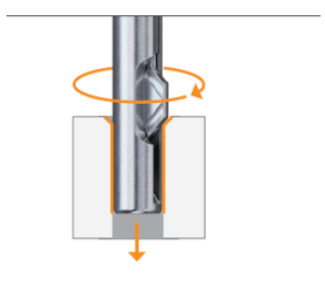
Front-Side Deburring
On entry, spring tension holds the blade in the extended cutting position, removing the burr from the front side of the pilot hole.
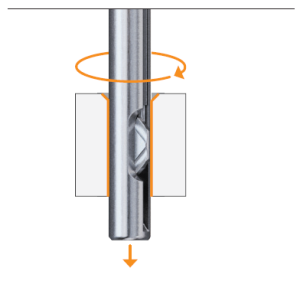
Automatic Retraction
Increased feed pressure overcomes the preset spring tension and retracts the blade while it passes through the bore. Blade geometry protects the bore surface.
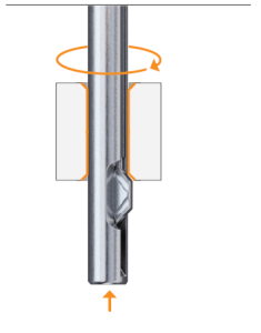
Back-Side Deburring
After exiting the pilot hole, the spring extends the blade again. The return stroke removes the burr from the rear side.
Select the Correct Blade Size & Geometry
Start with pilot-hole diameter, then choose cutting-edge material, coating and chip-former according to the workpiece material and process demand.
0.098″ ≤ d < 0.118″
PL geometry available in uncoated and coated versions.
Back deburring only.
0.118″ ≤ d < 0.197″
PL and ML chip-formers available.
d ≥ 0.197″
PL and ML chip-formers available.
Chip-Former Selection
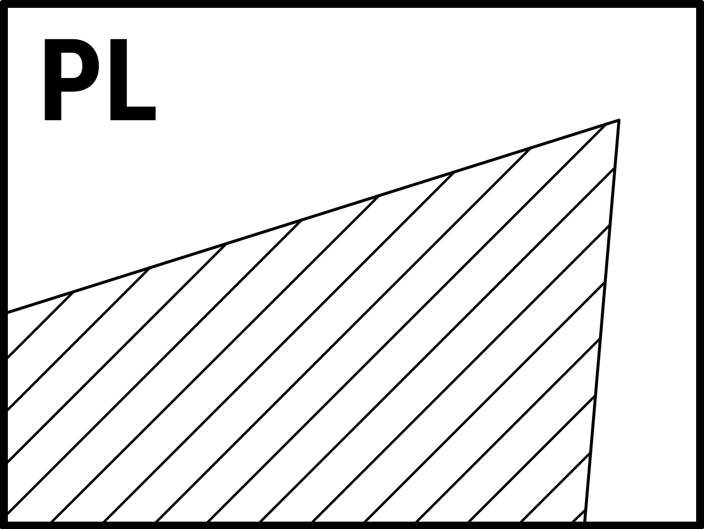 PL — Positive Land
General-purpose positive geometry suitable for ISO P, M, K, N, S and composite materials.
PL — Positive Land
General-purpose positive geometry suitable for ISO P, M, K, N, S and composite materials.
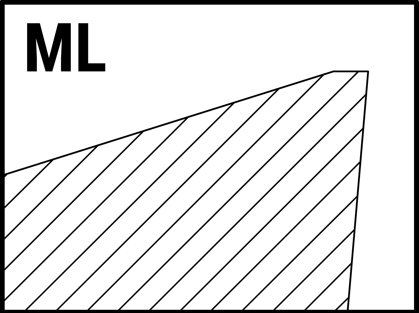 ML — Moderate Land
Stronger cutting edge for light roughing and demanding ISO P, M, K, S and H applications.
ML — Moderate Land
Stronger cutting edge for light roughing and demanding ISO P, M, K, S and H applications.
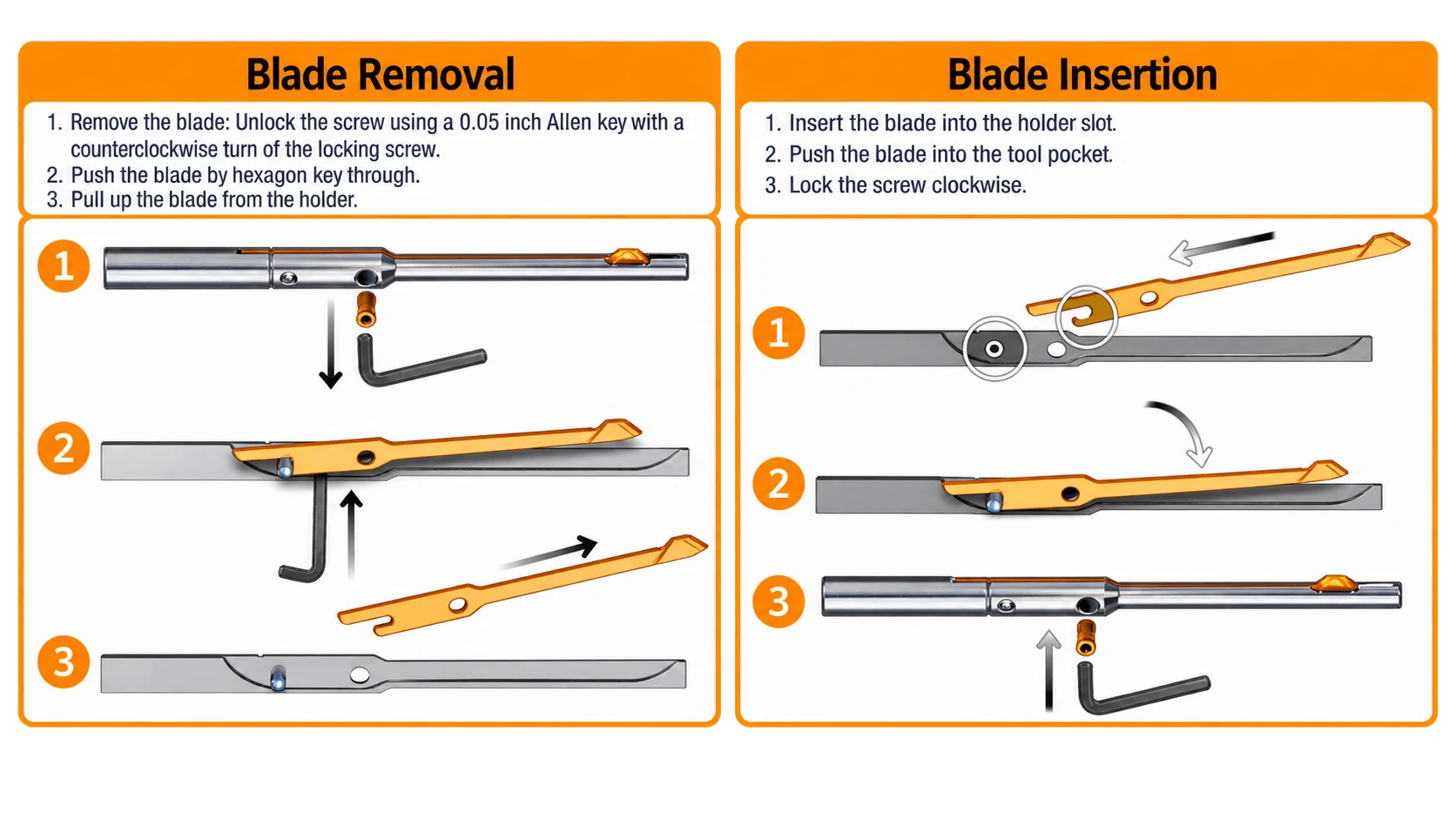
Blade Removal & Insertion
Follow the illustrated steps below to remove and insert a UBURR blade without taking the holder out of the machine.
UBURR Advisor & Application Calculators
Use the interactive UBURR application advisor to select the workpiece material, receive starting cutting data, identify the recommended holder / blade / complete set, calculate spindle speed and feed rate from the pilot-hole diameter, and validate inclined-surface or tube applications.
Select the workpiece material, blade configuration and tool setup to calculate UBURR starting parameters. The advisor can recommend the holder, blade and complete set from a pilot-hole diameter or screw thread, calculate RPM and feed rate automatically from the pilot-hole diameter and recommended cutting speed, and then validate inclined-surface or tube applications.
1. Select Workpiece
2. Cutting Data & Tool Setup
Tool Holder / Blade / Complete Set
Calculated Machine Values
Derived from selected source rangesApplication Calculators
Check the maximum allowable incline angle or validate UBURR use in a tube application. Units follow the single Display Units selector at the top of this advisor.
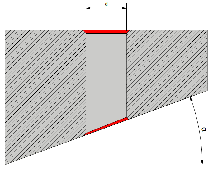
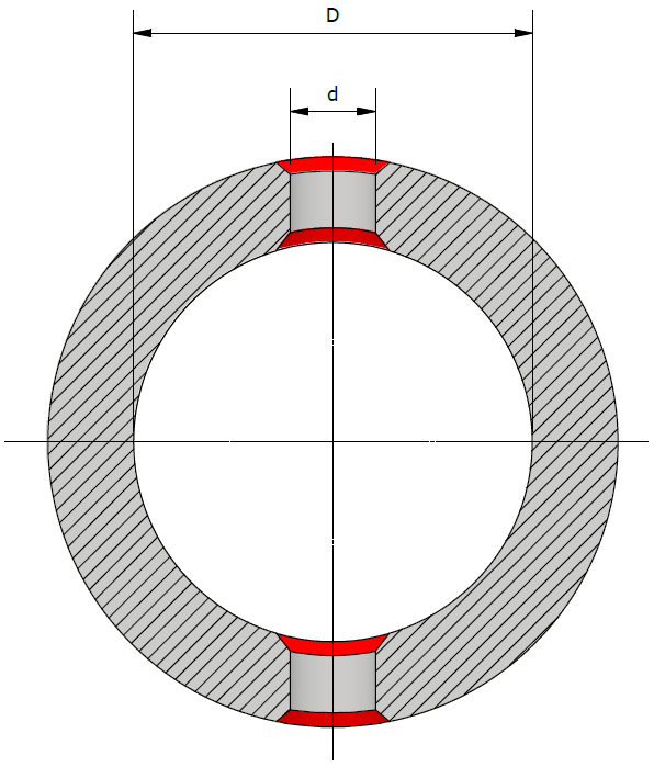
Inclined Surfaces, Tubes & Coolant Direction
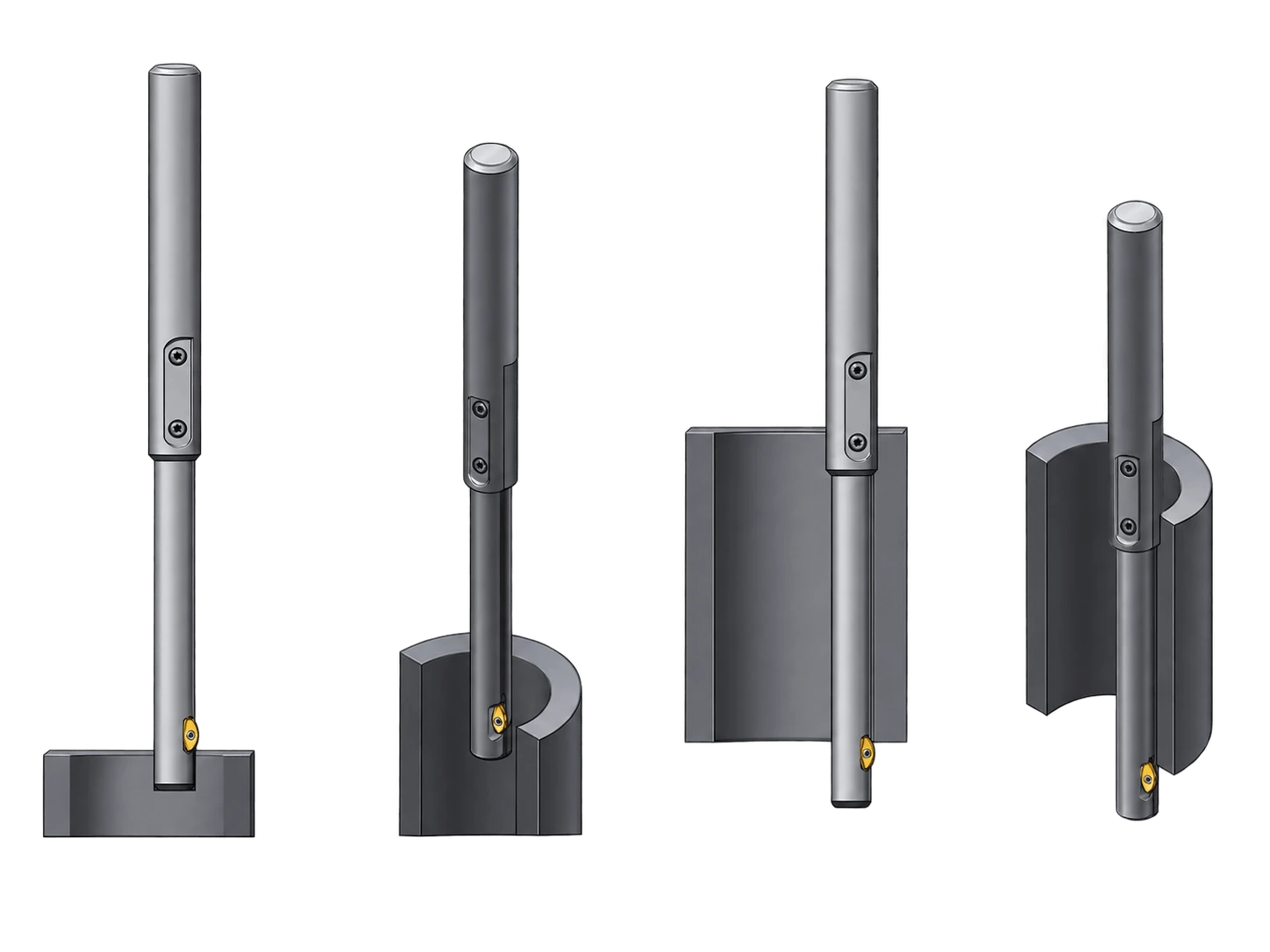
Sloped and cylindrical surfaces change the contact geometry of the blade. Verify the application before machining; an uneven chamfer is expected on non-perpendicular surfaces.
Rotation & Coolant
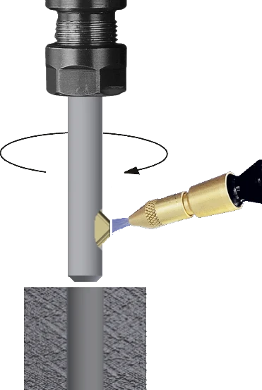
Use right-hand machining with clockwise rotation. Direct external coolant or air toward the blade to evacuate chips and swarf from the cutting zone.

Inclined Surface
The allowable slope depends on pilot-hole diameter and application geometry.
1.2 ≥ d × tan(α)
Cylindrical / Tube Surface
Verify the relation between tube diameter D and pilot diameter d before use.
0.75 ≥ 0.5 × (D − √(D² − d²))Use the UBURR Inclined / Tube Calculator
Use the integrated calculator above to calculate the maximum incline angle or validate tube geometry in metric or inch units.
Using the UBURR with Electric Hand Drills
UBURR is compatible with both CNC machines and electric hand drills, making it suitable for various operational setups and helping extend the tool’s usefulness beyond fixed machine applications.
Recommended Setup Approach
When using portable equipment, prioritize stability, alignment and controlled feed pressure. The same cutting principles remain valid: clockwise rotation, proper chip evacuation, and a stable approach through the pilot hole.
UBURR with an Electric Hand Tool
Watch UBURR being used with a portable electric hand tool. The short video gives a clear practical reference for setup, alignment and manual operation.
UBURR Programming Guidelines
Choose the required deburring cycle, review the actual tool movement, then load the corresponding macro inputs. The visual sequences below make the difference between front-and-back, back-only and interpolation programming much easier to understand.

Front + Back Deburring
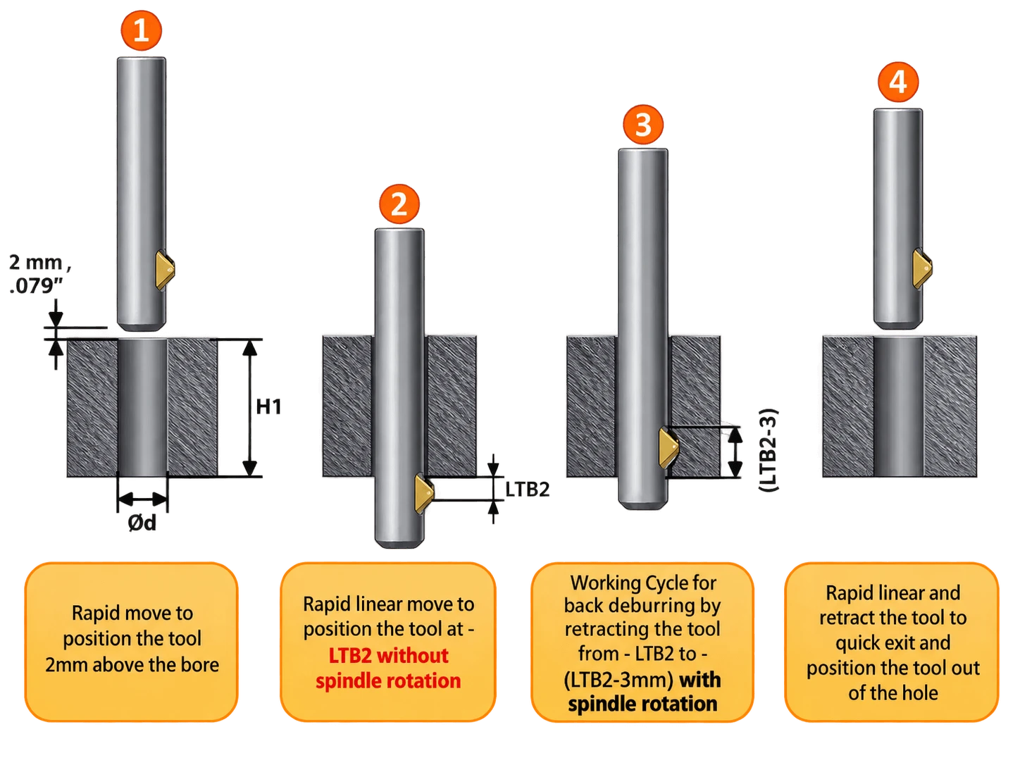
Insert the rotating UBURR through the pilot hole. The blade cuts the front edge, retracts through the bore, extends after exiting, and deburrs the rear edge during the return stroke.
Back Deburring Only
When front deburring is unnecessary, enter the pilot hole without spindle rotation. Start the working cycle only after the tool passes through the bore, then retract to machine the rear edge.
Deburring by Interpolation
Use interpolation when the process benefits from combining deburring functions into one tool and reducing additional tooling. Program the toolpath to follow the required edge while maintaining proper blade engagement.
| Parameter | Programming Input | Used In |
|---|---|---|
| #101 | Tool location / cycle start position | All cycles |
| #102 | Spindle speed according to the selected cutting recommendation | All cutting cycles |
| #103 | H1 — pilot-hole / workpiece length | All cycles |
| #104 | LTB1 according to the selected UBURR holder table | Front + Back |
| #105 | LTB2 according to the selected UBURR holder table | Front + Back / Back Only |
| #106 | Rapid linear feed used to position the tool | All cycles |
| #107 | Working-cycle feed according to the selected cutting recommendation | All cutting cycles |
Download the Correct Routine
Select the macro that matches the machine and cycle. These files are starting templates and must be checked against the actual CNC control syntax and machine setup.
Controlling the Chamfer Size
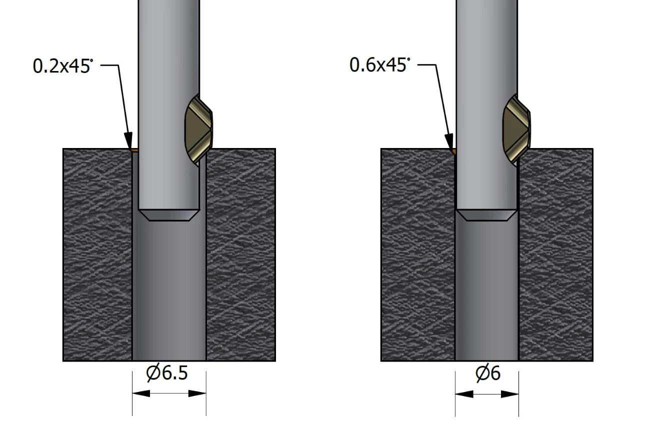
UBURR is primarily a deburring tool. The resulting edge break depends on tool selection, pilot-hole position within the holder range and working feed.
Continue Your UBURR Setup
Use the current product tables, macros, case studies and 3D models to complete the application setup.
Need Help Selecting a Holder, Blade or Starting Parameters?
For the best recommendation, provide the pilot-hole diameter, workpiece material and hardness, burr location and size, hole length, available machine / spindle data and required edge condition.