
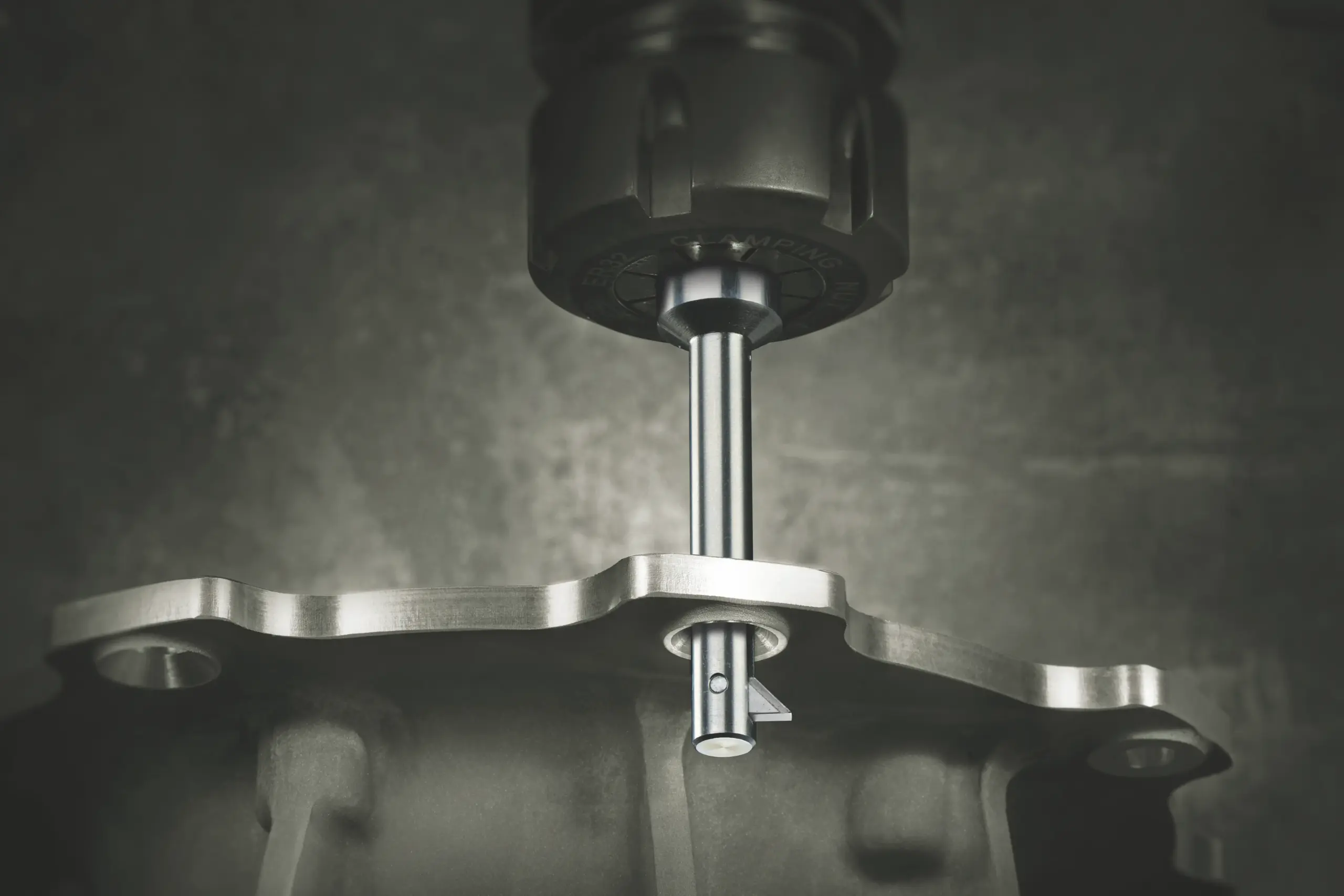
UCHAMF® Back Chamfering & Countersinking Tool
Machine hidden rear chamfers and countersinks through the existing pilot hole, without flipping the workpiece. Standard 82° / 90° inserts, special angles on request, on the coolant-actuated UBACK UX tool-holder.
UCHAMF / UX Series at a Glance
The UBACK range is organized into six series. Each series covers three pilot-hole sizes and defines the standard 82° / 90° UCHAMF countersink envelope, matching UX holders and RFC capacity.
| Series | Pilot-Hole Rangemm / inch | 82° Countersink Rangemm / inch | 90° Countersink Rangemm / inch | Standard UX Holders | RFCmm / inch |
|---|---|---|---|---|---|
| B | Ø8–10 mmØ0.315–0.394″ | Ø8.5–17 mmØ0.335–0.669″ | Ø8.5–18 mmØ0.335–0.709″ | UX2080 / UX2090 / UX2100 | 43 mm1.693″ |
| C | Ø11–13 mmØ0.433–0.512″ | Ø11.5–24 mmØ0.453–0.945″ | Ø11.5–25 mmØ0.453–0.984″ | UX3110 / UX3120 / UX3130 | 52 mm2.047″ |
| D | Ø14–16 mmØ0.551–0.630″ | Ø14.5–29 mmØ0.571–1.142″ | Ø14.5–31 mmØ0.571–1.220″ | UX4140 / UX4150 / UX4160 | 72.5 mm2.854″ |
| E | Ø17–19 mmØ0.669–0.748″ | Ø17.5–34 mmØ0.689–1.339″ | Ø17.5–37 mmØ0.689–1.457″ | UX5170 / UX5180 / UX5190 | 76.5 mm3.012″ |
| F | Ø20–22 mmØ0.787–0.866″ | Ø20.5–39 mmØ0.807–1.535″ | Ø20.5–42 mmØ0.807–1.654″ | UX6200 / UX6210 / UX6220 | 76.5 mm3.012″ |
| G | Ø23–25 mmØ0.906–0.984″ | Ø23.5–44 mmØ0.925–1.732″ | Ø23.5–47 mmØ0.925–1.850″ | UX7230 / UX7240 / UX7250 | 72 mm2.835″ |
Find the Correct 82° / 90° UCHAMF Insert
Enter the angle and the pilot Ød or countersink ØD you know. Add all three values for a final check; if no standard insert fits, contact us for a special.
Show / hide complete Standard Insert table
| Ød minmm / inch | 82° SKU | 82° Description | 82° ØDmaxmm / inch | 90° SKU | 90° Description | 90° ØDmaxmm / inch | Series |
|---|---|---|---|---|---|---|---|
| Ø8 mmØ0.315″ | UC2101 | UC-82-d080-B-PL-NCT | Ø15 mmØ0.591″ | UC2201 | UC-90-d080-B-PL-NCT | Ø16 mmØ0.630″ | B |
| Ø9 mmØ0.354″ | UC2102 | UC-82-d090-B-PL-NCT | Ø16 mmØ0.630″ | UC2202 | UC-90-d090-B-PL-NCT | Ø17 mmØ0.669″ | B |
| Ø10 mmØ0.394″ | UC2103 | UC-82-d100-B-PL-NCT | Ø17 mmØ0.669″ | UC2203 | UC-90-d100-B-PL-NCT | Ø18 mmØ0.709″ | B |
| Ø11 mmØ0.433″ | UC3101 | UC-82-d110-C-PL-NCT | Ø22 mmØ0.866″ | UC3201 | UC-90-d110-C-PL-NCT | Ø23 mmØ0.906″ | C |
| Ø12 mmØ0.472″ | UC3102 | UC-82-d120-C-PL-NCT | Ø23 mmØ0.906″ | UC3202 | UC-90-d120-C-PL-NCT | Ø24 mmØ0.945″ | C |
| Ø13 mmØ0.512″ | UC3103 | UC-82-d130-C-PL-NCT | Ø24 mmØ0.945″ | UC3203 | UC-90-d130-C-PL-NCT | Ø25 mmØ0.984″ | C |
| Ø14 mmØ0.551″ | UC4101 | UC-82-d140-D-PL-NCT | Ø27 mmØ1.063″ | UC4201 | UC-90-d140-D-PL-NCT | Ø29 mmØ1.142″ | D |
| Ø15 mmØ0.591″ | UC4102 | UC-82-d150-D-PL-NCT | Ø28 mmØ1.102″ | UC4202 | UC-90-d150-D-PL-NCT | Ø30 mmØ1.181″ | D |
| Ø16 mmØ0.630″ | UC4103 | UC-82-d160-D-PL-NCT | Ø29 mmØ1.142″ | UC4203 | UC-90-d160-D-PL-NCT | Ø31 mmØ1.220″ | D |
| Ø17 mmØ0.669″ | UC5101 | UC-82-d170-E-PL-NCT | Ø32 mmØ1.260″ | UC5201 | UC-90-d170-E-PL-NCT | Ø35 mmØ1.378″ | E |
| Ø18 mmØ0.709″ | UC5102 | UC-82-d180-E-PL-NCT | Ø33 mmØ1.299″ | UC5202 | UC-90-d180-E-PL-NCT | Ø36 mmØ1.417″ | E |
| Ø19 mmØ0.748″ | UC5103 | UC-82-d190-E-PL-NCT | Ø34 mmØ1.339″ | UC5203 | UC-90-d190-E-PL-NCT | Ø37 mmØ1.457″ | E |
| Ø20 mmØ0.787″ | UC6101 | UC-82-d200-F-PL-NCT | Ø37 mmØ1.457″ | UC6201 | UC-90-d200-F-PL-NCT | Ø40 mmØ1.575″ | F |
| Ø21 mmØ0.827″ | UC6102 | UC-82-d210-F-PL-NCT | Ø38 mmØ1.496″ | UC6202 | UC-90-d210-F-PL-NCT | Ø41 mmØ1.614″ | F |
| Ø22 mmØ0.866″ | UC6103 | UC-82-d220-F-PL-NCT | Ø39 mmØ1.535″ | UC6203 | UC-90-d220-F-PL-NCT | Ø42 mmØ1.654″ | F |
| Ø23 mmØ0.906″ | UC7101 | UC-82-d230-G-PL-NCT | Ø42 mmØ1.654″ | UC7201 | UC-90-d230-G-PL-NCT | Ø45 mmØ1.772″ | G |
| Ø24 mmØ0.945″ | UC7102 | UC-82-d240-G-PL-NCT | Ø43 mmØ1.693″ | UC7202 | UC-90-d240-G-PL-NCT | Ø46 mmØ1.811″ | G |
| Ø25 mmØ0.984″ | UC7103 | UC-82-d250-G-PL-NCT | Ø44 mmØ1.732″ | UC7203 | UC-90-d250-G-PL-NCT | Ø47 mmØ1.850″ | G |
How to Select the Correct UX Holder and UCHAMF Insert
Keep the process simple: pilot / holder first, then angle and ØD, then reach and series compatibility.
Start with Pilot Ød
Select the UX holder whose nominal / supported pilot range fits the through hole.
Example: Ød = 8.7 mm → Series B / UX2080Select Countersink Angle α
Choose 82° or 90° for a standard insert. Use a special-angle UC designation for application-specific requirements.
82° / 90° standard · special on requestDefine ØD & Reach
Enter the required countersink diameter ØD and pilot-hole length L. Verify the selected insert's ØDmax and holder RFC.
ØD ≤ ØDmax · L ≤ RFCVerify Series & Designation
Confirm the UC insert series matches the UX holder. For standard inserts, use the standard SKU; for special angles, use the generated UC designation.
UC-110-d080-B-PL-NCTChip-Formers, Coatings & Surface Treatments
The chip-former controls the cutting-edge geometry; the coating or surface treatment controls heat resistance, wear behavior, friction and material adhesion. Use this section to understand the codes used by the UCHAMF configurator and UC insert designation.
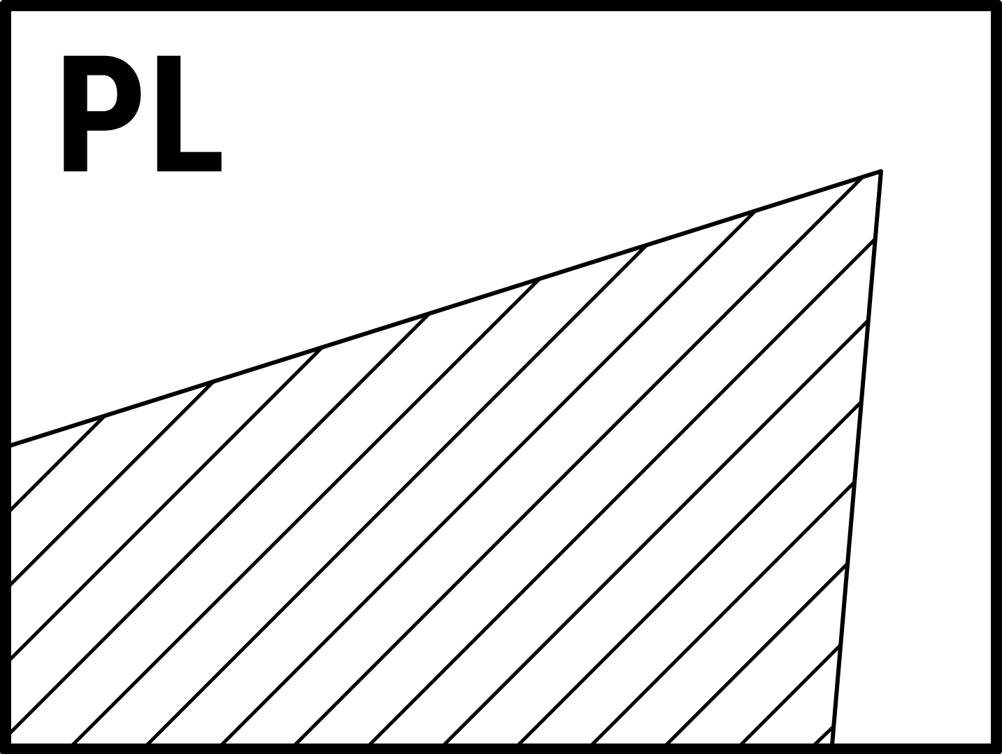
PL — Positive Cutting Land
Suitable for all-round purpose and ISO P, M, K, N and S materials.
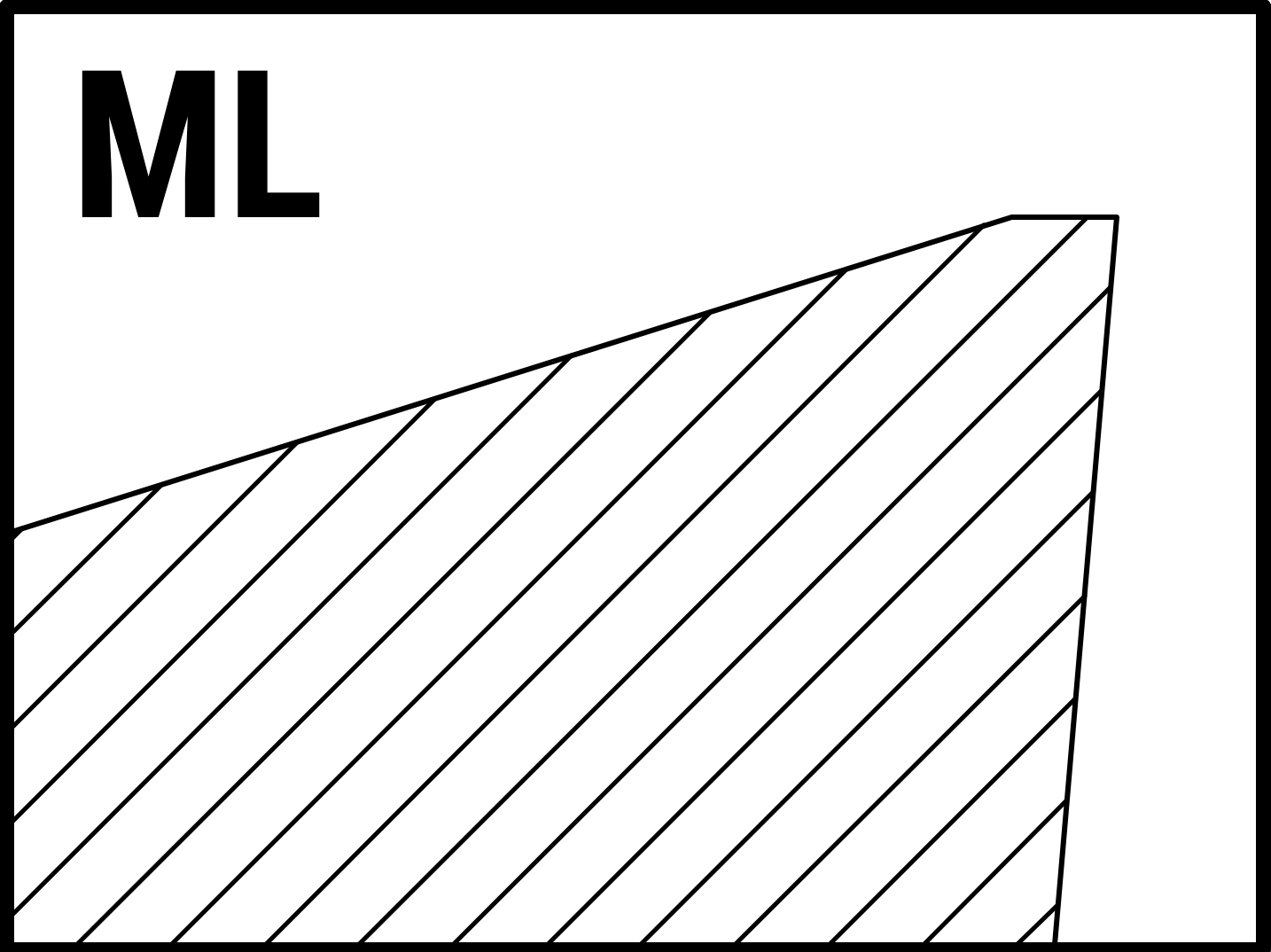
ML — Moderate Cutting Land
Suitable for ISO P, M, K, S and H materials.
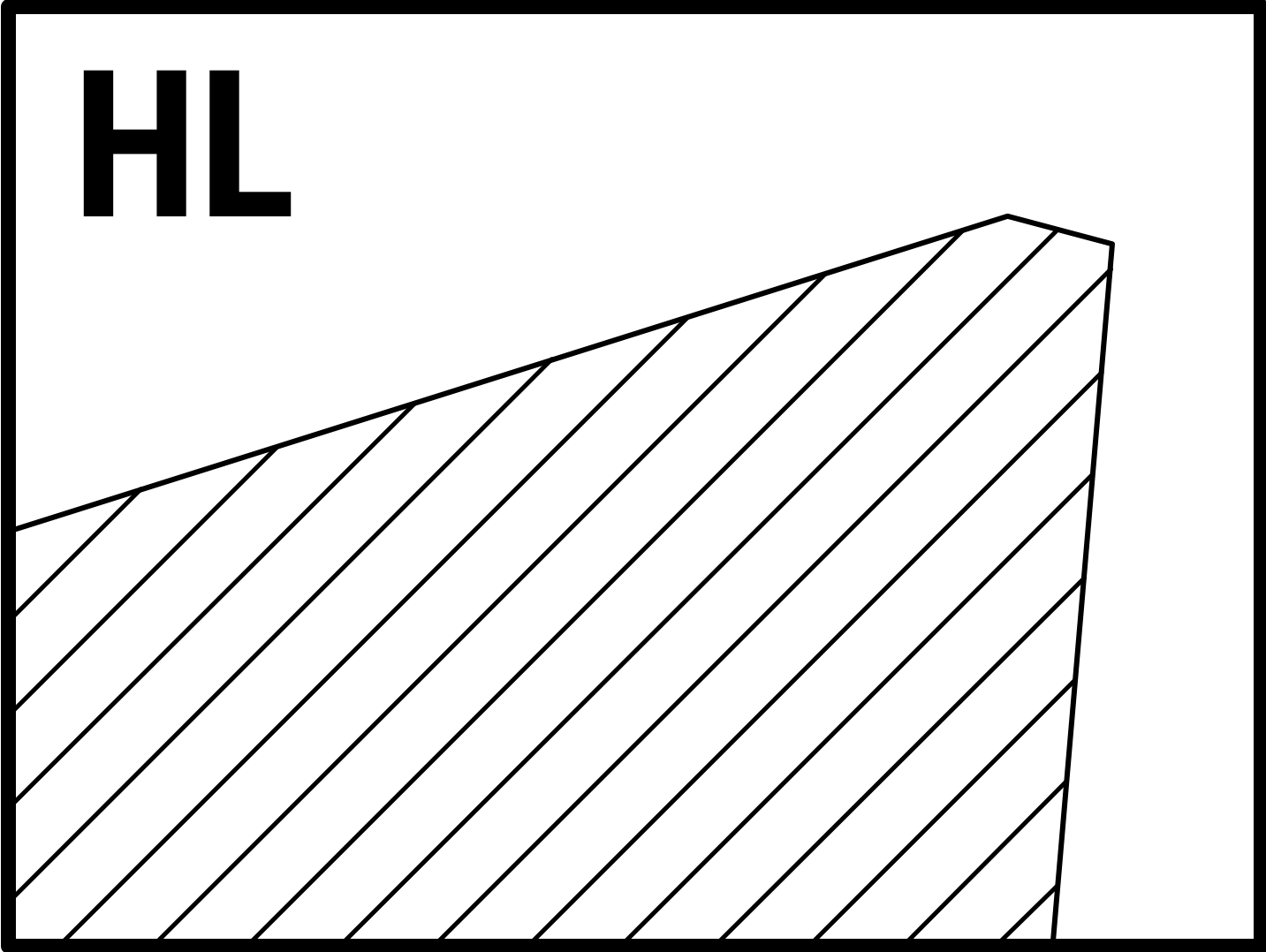
HL — Negative Cutting Land
Suitable for ISO P, M, K, S and H materials.
Coating Types & Surface Treatments
Comparison of NOGA coating / surface-treatment codes, key characteristics, typical applications and ISO material-group suitability.
| NOGA's Code | Coating | Key Features | Applications | Industries | Material Examples | ISO group | |||||
|---|---|---|---|---|---|---|---|---|---|---|---|
| P | M | K | N | S | H | ||||||
| NCT | TiAlN | Excellent thermal stability, oxidation resistance, and wear resistance. | High-speed cutting and general-purpose machining. Works in wet & dry conditions. | Aerospace, Automotive, General Engineering | AISI 304, 42CrMo4, Grey Cast Iron (GG), Ti6Al4V | ✓ | ✓ | ✓ | × | ✓ | ✓ |
| NCD | TiAlSiN | Very high hardness, extreme oxidation resistance (>1200°C). Excels in dry machining at high speeds. Suitable for hardened steels >45 Rc. | High-performance machining in demanding environments. | Aerospace, Automotive, Die & Mold | Inconel 718, AISI 4140, Ti6Al4V, Hastelloy | ✓ | ✓ | × | × | ✓ | ✓ |
| NCA | AlTiSiN | High hardness, thermal stability, and wear resistance. Works well in dry, high-speed cutting. Suitable for hardened steels >45 Rc. | High-speed machining in extreme conditions. | Aerospace, Automotive, Precision Engineering | AISI 316, AISI H13, Hastelloy | ✓ | ✓ | × | × | ✓ | ✓ |
| NCN | AlCrN | High oxidation resistance (to 1100°C), toughness, abrasion resistance. | General machining in abrasive / wet conditions. | Automotive, Aerospace, Die & Mold | AISI 304, AISI 1045, Grey Cast Iron (GG), AL6061, Die Steels | ✓ | ✓ | ✓ | ✓ | × | × |
| NCW | AlTiN | High hardness, wear resistance, thermal stability up to 1100°C. | Heavy-duty machining and high-speed cutting. Dry & abrasive conditions. | Aerospace, Automotive, Heavy Engineering | AISI 4340, M2 HSS, Grey Cast Iron (GG) | ✓ | ✓ | ✓ | × | ✓ | × |
| NCB | TiB₂ | Excellent thermal stability, hardness, and very high conductivity. Prevents material adhesion and BUE. | High-speed machining of non-ferrous metals. | Aerospace, Automotive, Electronics | AL7075, 6061-T6, Copper, Magnesium Alloys (AZ31), SiC composites | × | × | × | ✓ | ✓ | × |
| POL | Polishing (Surface Treatment) | Removes scratches, burrs and micro-defects. Produces smooth finish and reduces friction. | High-speed finishing of non-ferrous materials. Improves MRR and surface aesthetics. | Aerospace, Automotive | AL7075, 6061-T6, Copper, Magnesium Alloys (AZ31) | × | × | × | ✓ | × | × |
UCHAMF Configurator & G-Code Generator
Select UCHAMF in Step 1, then enter the feature: it checks pilot Ød, angle, ØD and L ≤ RFC, matches the UX holder, and outputs the UC designation and CNC program.
🔧 UBACK Configurator & G-Code Generator
USPOT / UCHAMF insert configurator · Tool-holder matching · CNC back counterboring & countersinking programs
Step 1: Select Insert Type
Choose the UBACK application you need. The configurator will build the exact insert designation and match the correct UX tool-holder.
Click an insert type to continue — the configurator opens automatically.
Step 2: Insert Configurator
Enter your application dimensions. All designation codes are generated in metric.
⚡ Quick Fill from Insert Designation (optional)
⚙ Configuration Parameters
📐 Technical Diagram
Step 3: Your Insert & Tool-Holder
Matched configuration based on your application. The insert series always matches the tool-holder series.
🔩 Insert
🛠 UX Tool-Holder
Step 4: Generate CNC Program
Build the back-machining cycle for your controller using the matched tool-holder and insert.
📊 Recommended Cutting Data
Generated G-Code Program
Disclaimer of Liability — CNC Programs
The CNC programs, cutting data, and 3D models generated by this tool are provided for reference and convenience only, as a starting point for process planning. They are generated automatically from the parameters entered and have not been verified for any specific machine, control, workpiece, fixture, or operating condition.
It is the sole responsibility of a qualified CNC programmer or operator to review, validate, and adapt every generated program before use — including verifying all coordinates, speeds, feeds, tool and coolant M-codes, clearances, and safety limits against the actual machine and setup. Every program must be run for the first time with appropriate caution, using reduced feed and rapid overrides, single-block execution, and a dry run without a workpiece.
To the fullest extent permitted by law, NOGA and its affiliates accept no responsibility or liability for any damage, injury, loss, or cost of any kind arising from the use of, or reliance on, the output of this tool, whether used as generated or after modification. Use of this tool constitutes acceptance of these terms.
Download 3D model
Choose what the STEP file should contain. Both options use the same datum: tool axis on Z, Z0 at the tool nose face.
Full UCHAMF Tool-Holder Reference
Search by UX SKU, pilot diameter, series, RFC, 82° / 90° ØDmax or spare-part code. Metric and inch values are shown together.
UCHAMF / UX Dimensional Drawing
Review FL, RFC, LTB2, pilot diameter and countersink geometry before using the holder table.

Tool-holder table · Metric / Inch
| Ød minmm / inch | SKU | Description | Series | ØDS h6mm / inch | FLmm / inch | RFCmm / inch | Hmm / inch | Lmm / inch | L1mm / inch | LTB2mm / inch | 82° ØDmaxmm / inch | 90° ØDmaxmm / inch | Piston Plug | Insert Screw |
|---|---|---|---|---|---|---|---|---|---|---|---|---|---|---|
| Ø8 mmØ0.315″ | UX2080 | UX-d080-B-C16-H62-L115 | B | Ø16 mmØ0.630″ | 17 mm0.669″ | 43 mm1.693″ | 62 mm2.441″ | 115 mm4.528″ | 53 mm2.087″ | 8.25 mm0.325″ | Ø15 mmØ0.591″ | Ø16 mmØ0.630″ | UX0011 / M5×6 | UX0005 / M2.5×0.35×7B |
| Ø9 mmØ0.354″ | UX2090 | UX-d090-B-C16-H62-L115 | B | Ø16 mmØ0.630″ | 17.8 mm0.701″ | 43 mm1.693″ | 62 mm2.441″ | 115 mm4.528″ | 53 mm2.087″ | 8.25 mm0.325″ | Ø16 mmØ0.630″ | Ø17 mmØ0.669″ | UX0011 / M5×6 | UX0005 / M2.5×0.35×7B |
| Ø10 mmØ0.394″ | UX2100 | UX-d100-B-C16-H62-L115 | B | Ø16 mmØ0.630″ | 18.8 mm0.740″ | 43 mm1.693″ | 62 mm2.441″ | 115 mm4.528″ | 53 mm2.087″ | 8.25 mm0.325″ | Ø17 mmØ0.669″ | Ø18 mmØ0.709″ | UX0011 / M5×6 | UX0005 / M2.5×0.35×7B |
| Ø11 mmØ0.433″ | UX3110 | UX-d110-C-C16-H80-L133 | C | Ø16 mmØ0.630″ | 27 mm1.063″ | 52 mm2.047″ | 80 mm3.150″ | 133 mm5.236″ | 53 mm2.087″ | 13.6 mm0.535″ | Ø22 mmØ0.866″ | Ø23 mmØ0.906″ | UX0011 / M5×6 | UX0006 / M3×0.35×10C |
| Ø12 mmØ0.472″ | UX3120 | UX-d120-C-C16-H80-L133 | C | Ø16 mmØ0.630″ | 27.3 mm1.075″ | 52 mm2.047″ | 80 mm3.150″ | 133 mm5.236″ | 53 mm2.087″ | 13.6 mm0.535″ | Ø23 mmØ0.906″ | Ø24 mmØ0.945″ | UX0011 / M5×6 | UX0006 / M3×0.35×10C |
| Ø13 mmØ0.512″ | UX3130 | UX-d130-C-C16-H80-L133 | C | Ø16 mmØ0.630″ | 28 mm1.102″ | 52 mm2.047″ | 80 mm3.150″ | 133 mm5.236″ | 53 mm2.087″ | 13.6 mm0.535″ | Ø24 mmØ0.945″ | Ø25 mmØ0.984″ | UX0011 / M5×6 | UX0006 / M3×0.35×10C |
| Ø14 mmØ0.551″ | UX4140 | UX-d140-D-C20-H105-L158 | D | Ø20 mmØ0.787″ | 32.5 mm1.280″ | 72.5 mm2.854″ | 105 mm4.134″ | 158 mm6.220″ | 53 mm2.087″ | 15.3 mm0.602″ | Ø27 mmØ1.063″ | Ø29 mmØ1.142″ | UX0012 / M6×6 | UX0007 / M3×0.35×13D |
| Ø15 mmØ0.591″ | UX4150 | UX-d150-D-C20-H105-L158 | D | Ø20 mmØ0.787″ | 32.5 mm1.280″ | 72.5 mm2.854″ | 105 mm4.134″ | 158 mm6.220″ | 53 mm2.087″ | 15.3 mm0.602″ | Ø28 mmØ1.102″ | Ø30 mmØ1.181″ | UX0012 / M6×6 | UX0007 / M3×0.35×13D |
| Ø16 mmØ0.630″ | UX4160 | UX-d160-D-C20-H105-L158 | D | Ø20 mmØ0.787″ | 32.5 mm1.280″ | 72.5 mm2.854″ | 105 mm4.134″ | 158 mm6.220″ | 53 mm2.087″ | 15.3 mm0.602″ | Ø29 mmØ1.142″ | Ø31 mmØ1.220″ | UX0012 / M6×6 | UX0007 / M3×0.35×13D |
| Ø17 mmØ0.669″ | UX5170 | UX-d170-E-C20-H115-L170 | E | Ø20 mmØ0.787″ | 38.5 mm1.516″ | 76.5 mm3.012″ | 115 mm4.528″ | 170 mm6.693″ | 55 mm2.165″ | 18 mm0.709″ | Ø32 mmØ1.260″ | Ø35 mmØ1.378″ | UX0012 / M6×6 | UX0008 / M3×0.35×16E |
| Ø18 mmØ0.709″ | UX5180 | UX-d180-E-C20-H115-L170 | E | Ø20 mmØ0.787″ | 38.5 mm1.516″ | 76.5 mm3.012″ | 115 mm4.528″ | 170 mm6.693″ | 55 mm2.165″ | 18 mm0.709″ | Ø33 mmØ1.299″ | Ø36 mmØ1.417″ | UX0012 / M6×6 | UX0008 / M3×0.35×16E |
| Ø19 mmØ0.748″ | UX5190 | UX-d190-E-C20-H115-L170 | E | Ø20 mmØ0.787″ | 38.5 mm1.516″ | 76.5 mm3.012″ | 115 mm4.528″ | 170 mm6.693″ | 55 mm2.165″ | 18 mm0.709″ | Ø34 mmØ1.339″ | Ø37 mmØ1.457″ | UX0012 / M6×6 | UX0008 / M3×0.35×16E |
| Ø20 mmØ0.787″ | UX6200 | UX-d200-F-C25-H120-L175 | F | Ø25 mmØ0.984″ | 43.5 mm1.713″ | 76.5 mm3.012″ | 120 mm4.724″ | 175 mm6.890″ | 55 mm2.165″ | 20 mm0.787″ | Ø37 mmØ1.457″ | Ø40 mmØ1.575″ | UX0013 / M8×6 | UX0009 / M4×0.5×19F |
| Ø21 mmØ0.827″ | UX6210 | UX-d210-F-C25-H120-L175 | F | Ø25 mmØ0.984″ | 43.5 mm1.713″ | 76.5 mm3.012″ | 120 mm4.724″ | 175 mm6.890″ | 55 mm2.165″ | 20 mm0.787″ | Ø38 mmØ1.496″ | Ø41 mmØ1.614″ | UX0013 / M8×6 | UX0009 / M4×0.5×19F |
| Ø22 mmØ0.866″ | UX6220 | UX-d220-F-C25-H120-L175 | F | Ø25 mmØ0.984″ | 43.5 mm1.713″ | 76.5 mm3.012″ | 120 mm4.724″ | 175 mm6.890″ | 55 mm2.165″ | 20 mm0.787″ | Ø39 mmØ1.535″ | Ø42 mmØ1.654″ | UX0013 / M8×6 | UX0009 / M4×0.5×19F |
| Ø23 mmØ0.906″ | UX7230 | UX-d230-G-C25-H120-L175 | G | Ø25 mmØ0.984″ | 48 mm1.890″ | 72 mm2.835″ | 120 mm4.724″ | 175 mm6.890″ | 55 mm2.165″ | 22 mm0.866″ | Ø42 mmØ1.654″ | Ø45 mmØ1.772″ | UX0013 / M8×6 | UX0010 / M4×0.5×21G |
| Ø24 mmØ0.945″ | UX7240 | UX-d240-G-C25-H120-L175 | G | Ø25 mmØ0.984″ | 48 mm1.890″ | 72 mm2.835″ | 120 mm4.724″ | 175 mm6.890″ | 55 mm2.165″ | 22 mm0.866″ | Ø43 mmØ1.693″ | Ø46 mmØ1.811″ | UX0013 / M8×6 | UX0010 / M4×0.5×21G |
| Ø25 mmØ0.984″ | UX7250 | UX-d250-G-C25-H120-L175 | G | Ø25 mmØ0.984″ | 48 mm1.890″ | 72 mm2.835″ | 120 mm4.724″ | 175 mm6.890″ | 55 mm2.165″ | 22 mm0.866″ | Ø44 mmØ1.732″ | Ø47 mmØ1.850″ | UX0013 / M8×6 | UX0010 / M4×0.5×21G |
UCHAMF at a glance
Screening values. The configurator confirms the exact holder and insert.
- Pilot-Hole Range
- Ø8–25 mm / 0.315–0.984″
- Standard Angles
- 82° and 90° · special angles on request
- 82° Countersink Range
- Ø8.5–44 mm / 0.335–1.732″
- 90° Countersink Range
- Ø8.5–47 mm / 0.335–1.850″
- Minimum Pressure
- 6 bar / 90 PSI
- Tool-Holder Family
- UBACK UX / DURASHIELD
Selection and technical links
Start with the Application — Not the Catalog Table
Start with pilot diameter, countersink angle and required ØD, then use the configurator, standard-insert table, holder data and coding references for verification.
Enter pilot diameter, ØD, pilot-hole length, angle and material. Match the UX holder and generate the UC insert designation.
Open configurator Check Standard InsertsSee the B–G series and all standard 82° / 90° UCHAMF SKUs with their maximum countersink diameters.
View range Selection LogicFollow four checks for pilot diameter, angle, countersink diameter, holder reach and series compatibility.
How to select Technical CenterProgramming, interrupted-cut guidance, insert replacement, cooling configurations, cutting data, chip-formers and coatings.
Open Technical CenterApplication examples
Typical rear edges UCHAMF chamfers and countersinks through the pilot hole.

Hidden Rear-Edge Chamfer
Chamfer the rear edge of a through hole from the front side of the workpiece without repositioning the component.

Back Countersinking
Create controlled rear countersinks through the existing pilot hole using the foldable UBACK mechanism.
Standard 82° / 90° Angles
Use standard UCHAMF insert SKUs for the two most common countersink angles and verify ØDmax by pilot-hole size.
Deep / Restricted Rear Access
Use RFC and LTB2 to verify that the holder reaches safely below the workpiece before the rear chamfering move.

Special-Angle Chamfers
For angles beyond the standard 82° and 90° range, configure an application-specific UCHAMF insert with the required angle, chip-former and coating.
How the UBACK mechanism works
Coolant, emulsion or air through the spindle (6 bar / 90 PSI minimum) opens the insert below the part and lets it fold back for a safe exit.
 Plays muted when in view
Enter with the Insert Folded
Move through the pilot hole with the insert retracted to protect the bore and cutting edge.
Move Below the Workpiece
Use FL, RFC and LTB2 to reach a safe position below the rear surface before engagement.
Actuate & Machine
Pressure deploys the insert. Approach the rear edge and machine the required 82°, 90° or special-angle chamfer / countersink.
Close & Retract
Move to the safe retract position, return the insert to transit state and exit through the pilot hole.
Understand the Holder and UCHAMF Insert Codes
The configurator creates the designation automatically. These diagrams are useful references for purchasing, engineering drawings and quotations.
Designation diagrams and ordering example

UX Tool-Holder Coding
Holder designation communicates pilot diameter, series, shank size, working height and overall length.

UCHAMF Insert Coding
UC designation identifies countersink angle, pilot / holder size, series, chip-former and coating.
Aluminum 7075 · 110° Countersink
Watch UCHAMF & UBACK in Action
UCHAMF machining hidden rear chamfers and countersinks through the pilot hole.
 Plays muted when in view
UCHAMF Back Chamfering with the UBACK System
See the foldable UBACK mechanism applied to rear chamfering / countersinking without flipping the workpiece.

DURASHIELD Tool-Holders
DURASHIELD identifies NOGA MT's premium holder platform. The UX holder family uses a passivated construction designed for corrosion resistance, structural integrity and demanding industrial service.
UCHAMF Selection Questions
Can UCHAMF machine a rear chamfer without turning or flipping the workpiece?
Yes. UCHAMF passes through the existing pilot hole with the insert folded, deploys below the part and machines the hidden rear chamfer / countersink from the same setup.
Which UCHAMF angles are standard?
82° and 90° are standard UCHAMF countersink angles. The standard SKUs shown on this page use PL chip-former and NCT coating.
Can UCHAMF be supplied with a special countersink angle?
Yes. Angles other than 82° and 90° can be produced as application-specific / semi-standard UCHAMF inserts. Use the configurator to create the UC designation and send the application drawing for confirmation.
What is the maximum countersink diameter?
It depends on pilot-hole size and countersink angle. The standard range reaches up to Ø44 mm / 1.732″ for 82° inserts and Ø47 mm / 1.850″ for 90° inserts. Verify the exact ØDmax in the standard-insert or holder table.
How do I select the correct UCHAMF insert?
Start with pilot-hole diameter and select the matching UX holder / series. Then select 82°, 90° or a special angle, verify the requested ØD is within the insert limit and confirm pilot-hole length L ≤ RFC.
How is the insert opened and closed?
The UBACK UX holder uses coolant / emulsion or air pressure to actuate the insert. Minimum pressure is 6 bar / 90 PSI.
What is the difference between LTB2 and RFC?
RFC is the available relief / reach for the cutting operation and is used for the L ≤ RFC compatibility check. LTB2 is the UCHAMF holder positioning reference used for the rear-side cycle.
Do the UCHAMF insert and UX tool-holder need the same series?
Yes. Series B–G identifies the compatible UBACK geometry family. The UCHAMF insert series must match the UX holder series.
Are the tool-holder and insert sold together?
No. UX tool-holders and UCHAMF inserts are sold separately.
Where are programming and cutting recommendations?
Use the UBACK Technical Center ↗ for continuous / interrupted-cut programming, insert replacement, cooling configurations, machining parameters, coatings, chip-formers and detailed cutting recommendations.
Have the Drawing? Configure UCHAMF First.
Start with pilot diameter, angle and ØD in the configurator. For special angles, unusual geometries or interrupted rear edges, send the workpiece drawing, material and machine details to NOGA MT.