
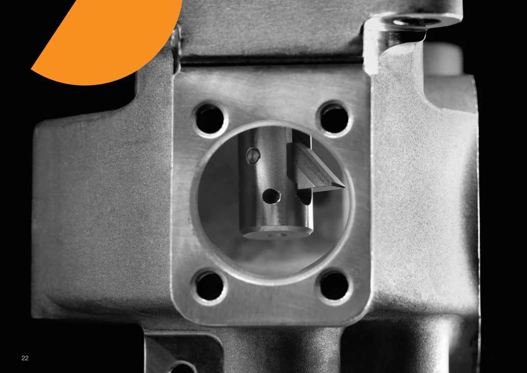
UBACK® Technical Center
Technical information for the complete UBACK platform: USPOT back counterboring / spotfacing, UCHAMF back chamfering / countersinking, CNC programming, cutting data, coolant setup, insert replacement, machining videos and drawings, RPM / feed guidance and the UBACK configurator.
Choose the UBACK Technical Information You Need
Jump directly to the technical topic you need, or open the UBACK configurator for USPOT / UCHAMF selection and CNC G-code support.
See USPOT, UCHAMF and UBACK mechanism videos plus the official dimensional drawings.
Operating PrinciplePressure-actuated foldable insert, pilot-hole transit and rear-side machining.
ProgrammingOfficial continuous and interrupted machining illustrations, plus programming guidance and example code.
Special GeometriesCylindrical, sloped, slot and shoulder applications with coolant guidance.
Machining ParametersInteractive RPM, cutting speed and feed advisor for USPOT and UCHAMF.
Full Cutting DataISO-group starting data for series B–G with stability adjustments.
Insert Replacement & CoolingReplacement procedure, spare parts and coolant / air / MQL configuration.
Coatings & Chip-FormersNCT/NCD/NCA/NCN/NCW/NCB/POL plus PL/ML/HL selection guidance.
UBACK Configurator & G-CodeConfigure USPOT / UCHAMF, verify application geometry and continue to CNC G-code support.
See the UBACK Process Before Programming It
Use the two application videos for USPOT and UCHAMF machining, then use the official dimensional drawings to understand the geometry that drives holder selection, RFC verification and CNC positioning. The mechanism and replacement videos are shown only in their dedicated technical sections below.
 USPOT MACHINING
USPOT in CNC Machining
Back Counterboring / SpotfacingReal rear-side flat-bottom machining through the existing pilot hole.
 UCHAMF MACHINING
UCHAMF in CNC Machining
Back Chamfering / CountersinkingSee the UBACK mechanism applied to rear chamfering and countersinking.
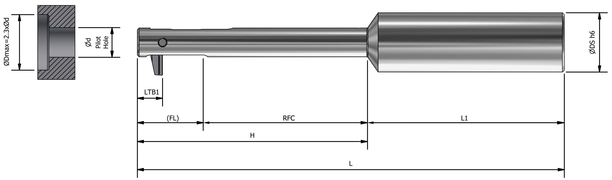
Back Counterbore / Spotface Geometry
USPOT Machining IllustrationUse the drawing to define the rear-side flat-bottom feature and verify the geometry before configuring the application.

Back Chamfer / Countersink Geometry
UCHAMF Machining IllustrationUse the standard 82° or 90° angle—or a special angle—to define the required rear chamfer while verifying holder reach and transit clearance.
How the UBACK System Works
UBACK UX holders are designed for automated CNC rear-side operations. The foldable insert passes through the pilot hole, is actuated after reaching the rear side and then performs the required USPOT or UCHAMF operation.
 UBACK MECHANISM · AUTOPLAY WHEN VISIBLE
Watch the Insert Open, Cut & Retract
The pressure-actuated mechanism lets the insert pass through the pilot hole in its transit position and machine the hidden rear feature once it is below the workpiece.
CNC Automated Operation
Designed for machine-controlled rear-side machining rather than a manual back-side setup.
Pressure Actuation
Coolant, emulsion or air can actuate the mechanism. Minimum pressure: 6 bar / 90 PSI.
Pilot-Hole Protection
The holder geometry is designed to pass through the pilot hole without damaging the bore surface.
Two Insert Families
USPOT performs flat-bottom back counterboring / spotfacing; UCHAMF performs back chamfering / countersinking.
Continuous & Interrupted-Cut Programming
The fundamental movement sequence is shared by USPOT and UCHAMF. Use the official UBACK machining illustrations together with the step-by-step sequence below. For interrupted cutting, the critical difference is the coolant strategy during the cutting portion of the cycle.
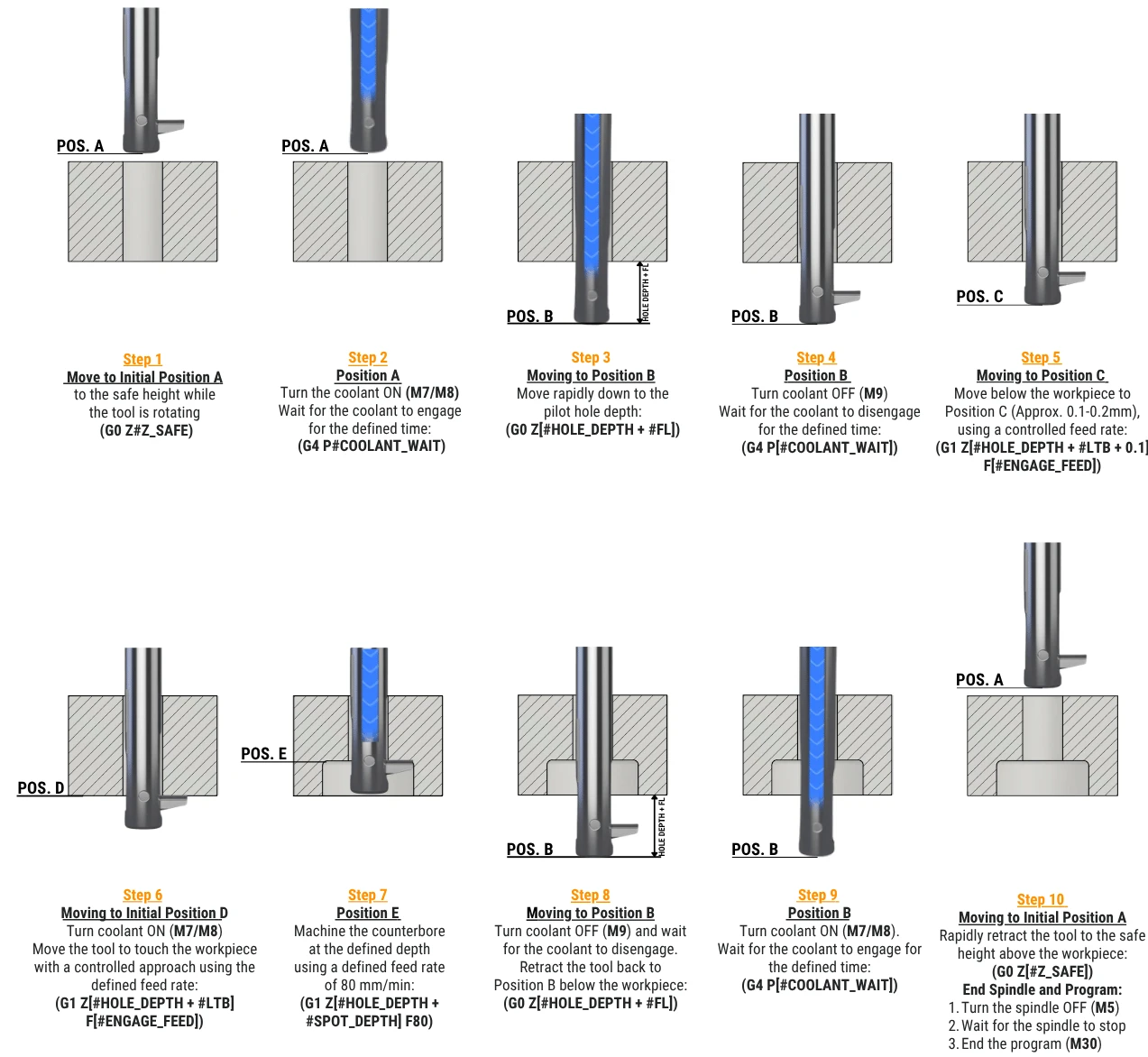
Continuous Cut
Use FL and rear-face position to move the folded insert safely below the workpiece, deploy it, machine the rear feature and return to the transit position.
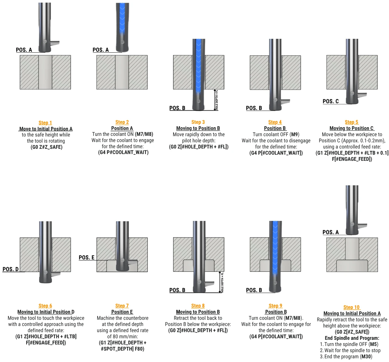
Interrupted Cut
Use the same overall motion sequence, but adapt the cutting portion of the cycle so pressure / coolant behavior does not interfere with an interrupted cutting path.
Rear-Surface Geometry Changes the Machining Strategy
Use these examples before selecting final cutting parameters. Continuous, sloped and fully interrupted rear surfaces do not use exactly the same coolant strategy or starting data.
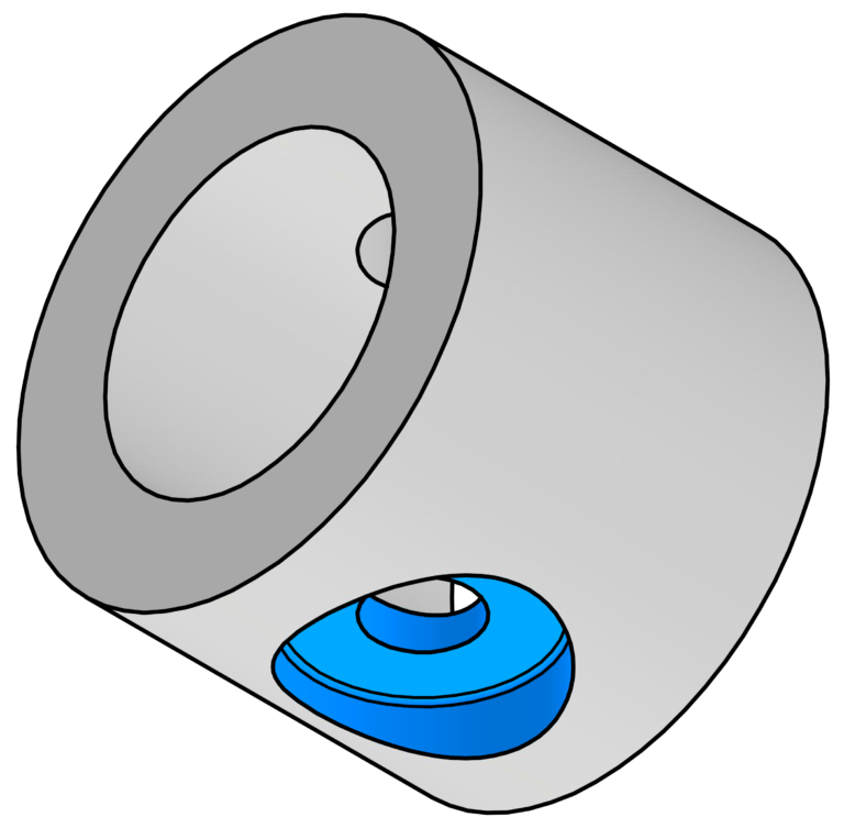
Cylindrical Bore
Continuous rear-side cutting with stable circumferential engagement.
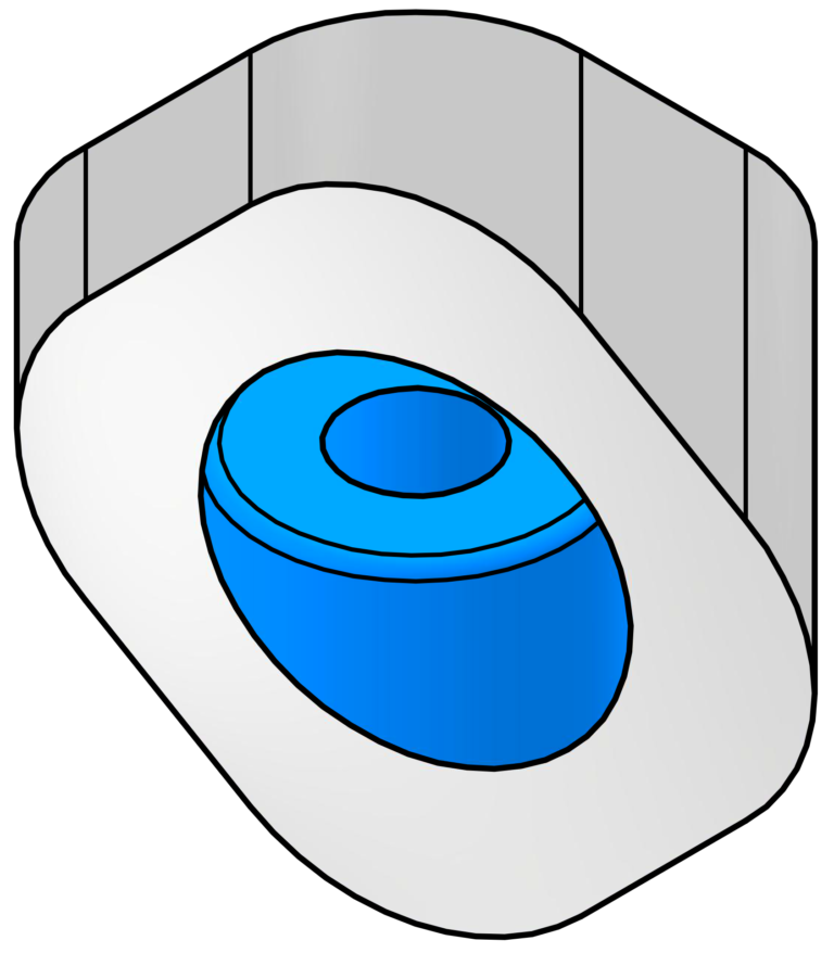
Sloped Surface
Variable insert engagement as the cutting edge moves across an inclined rear face.
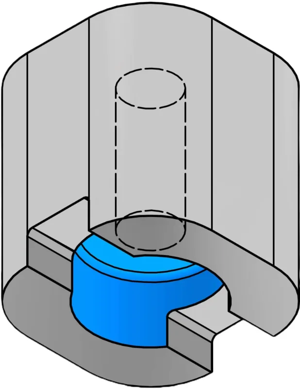
Slot
Fully interrupted engagement as the cutting edge crosses an open slot.
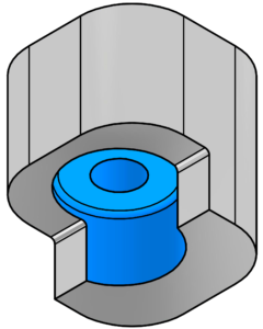
Shoulder — Type A
Fully interrupted shoulder geometry with reduced cutting stability.
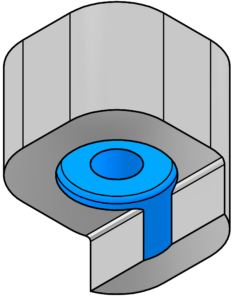
Shoulder — Type B
Alternative fully interrupted shoulder condition with repeated entry and exit.
| Rear-Surface Condition | Starting Data | Coolant During Cutting | Programming / Stability Note |
|---|---|---|---|
| Continuous cylindrical surface | Use normal UBACK recommendation. | Internal coolant / material recommendation. | Standard continuous-cut sequence. |
| Sloped surface | Start from the normal recommendation; reduce if engagement is unstable. | External coolant only. | Monitor entry load because engagement changes across the slope. |
| Fully interrupted slot | Reduce starting speed and feed by 50%. | External coolant only. | Confirm rigidity and repeatable insert engagement before increasing data. |
| Fully interrupted shoulder | Reduce starting speed and feed by 50%. | External coolant only. | Use the interrupted-cut programming sequence and increase parameters gradually. |
Calculate RPM & Feed from the UBACK Cutting Recommendations
Select the application, ISO material group, UX holder series and actual cutting diameter. The advisor converts the published UBACK starting recommendations into practical spindle speed and linear feed values.
Application Inputs
Enter the actual machining condition. Verify holder / insert geometry and dimensional limits separately before machining.
Recommended Starting Window
The result below is calculated from the published UBACK ISO-group data and adjusted for the selected application and stability condition.
- Select the application parameters and calculate.
Complete Machining Recommendation Table
The complete published UBACK material table is shown as individual searchable conditions. Filter by ISO group or search directly by material, condition, AISI / SAE / ASTM, DIN, chip-former or coolant.
| ISO | Material | Detail / Structure | Condition | AISI / SAE / ASTM | DIN W.-Nr. | vc Cutting Speed m/min / sfm |
Series B fr mm/t / ipt |
Series C fr mm/t / ipt |
Series D fr mm/t / ipt |
Series E fr mm/t / ipt |
Series F fr mm/t / ipt |
Series G fr mm/t / ipt |
Recommended Chip-Former |
Coolant |
|---|---|---|---|---|---|---|---|---|---|---|---|---|---|---|
| P | Non-alloy steel / cast steel / free-cutting steel | <0.25% C | Annealed | 1020 | 1.0044 | 60–120197–394 sfm | 0.030.0012″ | 0.040.0016″ | 0.050.0020″ | 0.070.0028″ | 0.080.0031″ | 0.090.0035″ | PL / ML | Air / Wet |
| P | Non-alloy steel / cast steel / free-cutting steel | ≥0.25% C | Annealed | 1035 | 1.0501 | 60–120197–394 sfm | 0.030.0012″ | 0.040.0016″ | 0.050.0020″ | 0.070.0028″ | 0.080.0031″ | 0.090.0035″ | PL / ML | Air / Wet |
| P | Non-alloy steel / cast steel / free-cutting steel | <0.55% C | Quenched & tempered | 1045 | 1.1201 | 60–120197–394 sfm | 0.030.0012″ | 0.040.0016″ | 0.050.0020″ | 0.070.0028″ | 0.080.0031″ | 0.090.0035″ | PL / ML | Air / Wet |
| P | Non-alloy steel / cast steel / free-cutting steel | ≥0.55% C | Annealed | 1055 | 1.0535 | 60–120197–394 sfm | 0.030.0012″ | 0.040.0016″ | 0.050.0020″ | 0.070.0028″ | 0.080.0031″ | 0.090.0035″ | PL / ML | Air / Wet |
| P | Non-alloy steel / cast steel / free-cutting steel | ≥0.55% C | Quenched & tempered | 1060 | 1.1221 | 60–120197–394 sfm | 0.030.0012″ | 0.040.0016″ | 0.050.0020″ | 0.070.0028″ | 0.080.0031″ | 0.090.0035″ | PL / ML | Air / Wet |
| P | Low-alloy / cast steel (<5% alloying elements) | — | Annealed | G92600 | 1.5028 | 50–120164–394 sfm | 0.030.0012″ | 0.040.0016″ | 0.050.0020″ | 0.070.0028″ | 0.080.0031″ | 0.090.0035″ | PL / ML | Air / Wet |
| P | Low-alloy / cast steel (<5% alloying elements) | — | Quenched & tempered | 4130 | 1.7218 | 50–120164–394 sfm | 0.030.0012″ | 0.040.0016″ | 0.050.0020″ | 0.070.0028″ | 0.080.0031″ | 0.090.0035″ | PL / ML | Air / Wet |
| P | Low-alloy / cast steel (<5% alloying elements) | — | Quenched & tempered | 4142 | 1.2332 | 50–120164–394 sfm | 0.030.0012″ | 0.040.0016″ | 0.050.0020″ | 0.070.0028″ | 0.080.0031″ | 0.090.0035″ | PL / ML | Air / Wet |
| P | Low-alloy / cast steel (<5% alloying elements) | — | Quenched & tempered | 5045 | 1.7006 | 50–100164–328 sfm | 0.030.0012″ | 0.040.0016″ | 0.050.0020″ | 0.070.0028″ | 0.080.0031″ | 0.090.0035″ | PL / ML | Air / Wet |
| P | High-alloy steel / cast steel / tool steel | — | Annealed | H13 | 1.2344 | 40–90131–295 sfm | 0.020.0008″ | 0.030.0012″ | 0.040.0016″ | 0.050.0020″ | 0.060.0024″ | 0.080.0031″ | PL / ML | Air / Wet |
| P | High-alloy steel / cast steel / tool steel | — | Quenched & tempered | M33 | 1.3249 | 40–90131–295 sfm | 0.020.0008″ | 0.030.0012″ | 0.040.0016″ | 0.050.0020″ | 0.060.0024″ | 0.080.0031″ | PL / ML | Air / Wet |
| P | Stainless steel / cast steel | Ferritic / martensitic | — | 420 | 1.4021 | 40–90131–295 sfm | 0.020.0008″ | 0.030.0012″ | 0.040.0016″ | 0.050.0020″ | 0.060.0024″ | 0.080.0031″ | PL / ML | Air / Wet |
| M | Stainless steel | Austenitic / duplex | — | 304L | 1.4306 | 50–100164–328 sfm | 0.030.0012″ | 0.040.0016″ | 0.050.0020″ | 0.070.0028″ | 0.080.0031″ | 0.090.0035″ | PL | Wet |
| K | Gray cast iron (GG) | Ferritic / pearlitic | — | Class 25 | 0.6015 | 60–120197–394 sfm | 0.030.0012″ | 0.040.0016″ | 0.050.0020″ | 0.070.0028″ | 0.080.0031″ | 0.090.0035″ | PL | Air / Wet |
| K | Gray cast iron (GG) | Pearlitic / martensitic | — | Grade H20 | 36037 | 60–120197–394 sfm | 0.030.0012″ | 0.040.0016″ | 0.050.0020″ | 0.070.0028″ | 0.080.0031″ | 0.090.0035″ | PL | Air / Wet |
| K | Nodular cast iron (GGG) | Ferritic | — | 60-40-18 | 0.7043 | 50–100164–328 sfm | 0.020.0008″ | 0.030.0012″ | 0.040.0016″ | 0.050.0020″ | 0.060.0024″ | 0.080.0031″ | PL | Air / Wet |
| K | Nodular cast iron (GGG) | Pearlitic | — | F33500 | 0.705 | 50–100164–328 sfm | 0.020.0008″ | 0.030.0012″ | 0.040.0016″ | 0.050.0020″ | 0.060.0024″ | 0.080.0031″ | PL | Air / Wet |
| K | Malleable cast iron | Ferritic | — | A47 | 0.8135 | 50–100164–328 sfm | 0.020.0008″ | 0.030.0012″ | 0.040.0016″ | 0.050.0020″ | 0.060.0024″ | 0.080.0031″ | PL | Air / Wet |
| K | Malleable cast iron | Pearlitic | — | A220 Class | 0.8155 | 50–100164–328 sfm | 0.020.0008″ | 0.030.0012″ | 0.040.0016″ | 0.050.0020″ | 0.060.0024″ | 0.080.0031″ | PL | Air / Wet |
| N | Aluminum wrought alloys | Not hardenable | — | 5005 | 3.3315 | 100–160328–525 sfm | 0.050.0020″ | 0.060.0024″ | 0.080.0031″ | 0.100.0039″ | 0.120.0047″ | 0.140.0055″ | PL | Wet |
| N | Aluminum wrought alloys | Hardenable | — | 7075 | 3.4365 | 100–160328–525 sfm | 0.050.0020″ | 0.060.0024″ | 0.080.0031″ | 0.100.0039″ | 0.120.0047″ | 0.140.0055″ | PL | Wet |
| N | Aluminum cast alloys | ≤12% Si | Not hardenable | 518 | 3.3292 | 100–160328–525 sfm | 0.050.0020″ | 0.060.0024″ | 0.080.0031″ | 0.100.0039″ | 0.120.0047″ | 0.140.0055″ | PL | Wet |
| N | Aluminum cast alloys | ≤12% Si | Hardenable | 515 | 3.3241 | 100–160328–525 sfm | 0.050.0020″ | 0.060.0024″ | 0.080.0031″ | 0.100.0039″ | 0.120.0047″ | 0.140.0055″ | PL | Wet |
| N | Aluminum cast alloys | >12% Si | High temperature | 390 | — | 100–160328–525 sfm | 0.050.0020″ | 0.060.0024″ | 0.080.0031″ | 0.100.0039″ | 0.120.0047″ | 0.140.0055″ | PL | Wet |
| N | Copper alloys | >1% Pb | Free cutting | C36000 | 2.0375 | 90–130295–427 sfm | 0.050.0020″ | 0.060.0024″ | 0.080.0031″ | 0.100.0039″ | 0.120.0047″ | 0.140.0055″ | PL | Wet |
| N | Copper alloys | — | Brass | C22000 | 2.023 | 90–130295–427 sfm | 0.050.0020″ | 0.060.0024″ | 0.080.0031″ | 0.100.0039″ | 0.120.0047″ | 0.140.0055″ | PL | Wet |
| N | Copper alloys | — | Electrolytic copper | C63000 | 2.0966 | 90–130295–427 sfm | 0.050.0020″ | 0.060.0024″ | 0.080.0031″ | 0.100.0039″ | 0.120.0047″ | 0.140.0055″ | PL | Wet |
| N | Non-metallic | Duroplastics / fiber plastics | — | Bakelite | — | 180–305591–1001 sfm | 0.050.0020″ | 0.060.0024″ | 0.080.0031″ | 0.100.0039″ | 0.120.0047″ | 0.140.0055″ | PL | Wet |
| N | Non-metallic | Hard rubber | — | Ebonite | — | 180–305591–1001 sfm | 0.050.0020″ | 0.060.0024″ | 0.080.0031″ | 0.100.0039″ | 0.120.0047″ | 0.140.0055″ | PL | Wet |
| S | High-temperature alloys | Fe based | Annealed | 330 | 1.4864 | 40–80131–262 sfm | 0.020.0008″ | 0.030.0012″ | 0.040.0016″ | 0.050.0020″ | 0.060.0024″ | 0.080.0031″ | PL / ML | Wet |
| S | High-temperature alloys | Fe based | Hardened | S590 | 1.4977 | 40–80131–262 sfm | 0.020.0008″ | 0.030.0012″ | 0.040.0016″ | 0.050.0020″ | 0.060.0024″ | 0.080.0031″ | PL / ML | Wet |
| S | High-temperature alloys | Ni / Co based | Annealed | Incoloy 825 | 2.4858 | 25–4082–131 sfm | 0.020.0008″ | 0.030.0012″ | 0.040.0016″ | 0.050.0020″ | 0.060.0024″ | 0.080.0031″ | PL / ML | Wet |
| S | High-temperature alloys | Ni / Co based | Hardened | Inconel 718 | 2.4668 | 25–4082–131 sfm | 0.020.0008″ | 0.030.0012″ | 0.040.0016″ | 0.050.0020″ | 0.060.0024″ | 0.080.0031″ | PL / ML | Wet |
| S | High-temperature alloys | Ni / Co based | Cast | Nimocast K24 | 2.4674 | 25–4082–131 sfm | 0.020.0008″ | 0.030.0012″ | 0.040.0016″ | 0.050.0020″ | 0.060.0024″ | 0.080.0031″ | PL / ML | Wet |
| S | Titanium alloys | Pure | — | Titanium Gr. 1 | 3.7024 | 30–6098–197 sfm | 0.020.0008″ | 0.030.0012″ | 0.040.0016″ | 0.050.0020″ | 0.060.0024″ | 0.080.0031″ | PL / ML | Wet |
| S | Titanium alloys | Alpha + beta alloys | Hardened | Titanium Gr. 5 | 3.7165 | 30–6098–197 sfm | 0.020.0008″ | 0.030.0012″ | 0.040.0016″ | 0.050.0020″ | 0.060.0024″ | 0.080.0031″ | PL / ML | Wet |
| H | Hardened steel | — | Hardened | HARDOX 500 | — | 30–5098–164 sfm | 0.020.0008″ | 0.020.0008″ | 0.030.0012″ | 0.040.0016″ | 0.050.0020″ | 0.060.0024″ | ML / HL | Air |
| H | Hardened steel | — | Hardened | HARDOX Extreme | — | 30–4098–131 sfm | 0.020.0008″ | 0.020.0008″ | 0.030.0012″ | 0.040.0016″ | 0.050.0020″ | 0.060.0024″ | ML / HL | Air |
| H | Chilled cast iron | — | Cast | A532 IIIA 25% Cr | 0.965 | 45–50148–164 sfm | 0.020.0008″ | 0.020.0008″ | 0.030.0012″ | 0.040.0016″ | 0.050.0020″ | 0.060.0024″ | ML / HL | Air |
| H | Cast iron | — | Hardened | A532 IID 20% CrMo | 0.9645 | 30–5098–164 sfm | 0.020.0008″ | 0.020.0008″ | 0.030.0012″ | 0.040.0016″ | 0.050.0020″ | 0.060.0024″ | ML / HL | Air |
Service the UBACK Insert and Configure the Correct Pressure Medium
UBACK inserts are replaced using the standardized pin, key and clamping-screw method without an additional mounting fixture. The same replacement principle applies to USPOT and UCHAMF. The UX holder can then be configured for emulsion / coolant, air or MQL according to the machine and application.
UBACK Insert Replacement
The replacement pin holds the insert in position so it cannot retract while the clamping screw is loosened. After removing the used insert, clean the seating pocket, install the correct replacement insert and verify free opening / closing before production.
 INSERT REPLACEMENT · AUTOPLAY WHEN VISIBLE
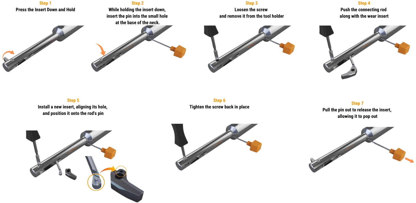
Used to secure the insert and prevent retraction while the clamping screw is being removed.
Use the correct service key supplied / specified for the UBACK clamping screw. The replacement method is common to USPOT and UCHAMF.
| UX Series | Pilot-Hole Range | Insert Clamping Screw | Piston / Coolant Plug | Service Note |
|---|---|---|---|---|
| B | Ø8–10 mm | UX0005 M2.5 × 0.35 × 7B | UX0011 M5 × 6 | Used on UX2080 / UX2090 / UX2100. |
| C | Ø11–13 mm | UX0006 M3 × 0.35 × 10C | UX0011 M5 × 6 | Used on UX3110 / UX3120 / UX3130. |
| D | Ø14–16 mm | UX0007 M3 × 0.35 × 13D | UX0012 M6 × 6 | Used on UX4140 / UX4150 / UX4160. |
| E | Ø17–19 mm | UX0008 M3 × 0.35 × 16E | UX0012 M6 × 6 | Used on UX5170 / UX5180 / UX5190. |
| F | Ø20–22 mm | UX0009 M4 × 0.5 × 19F | UX0013 M8 × 6 | Used on UX6200 / UX6210 / UX6220. |
| G | Ø23–25 mm | UX0010 M4 × 0.5 × 21G | UX0013 M8 × 6 | Used on UX7230 / UX7240 / UX7250. |
Configuring UBACK Tool-Holders for Different Cooling Systems
UBACK tool-holders can control insert retraction using emulsion / coolant, air or Minimum Quantity Lubrication (MQL). For air or MQL operation, seal the tool-holder coolant inlet with the supplied plug set screw. Minimum system actuation pressure remains 6 bar / 90 PSI.
UBACK tool-holders control insert retraction using emulsion / coolant, compressed air or Minimum Quantity Lubrication (MQL). For air or MQL operation, seal the tool-holder coolant inlet with the supplied plug set screw.
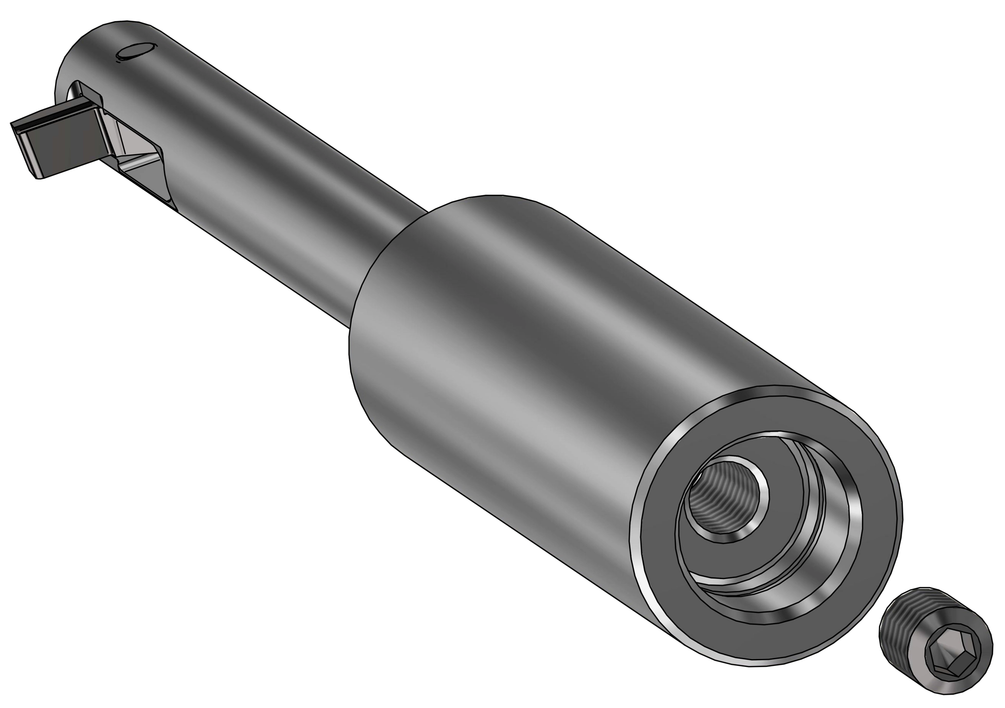
Standard UBACK pressure-actuation configuration using the machine's coolant / emulsion supply through the spindle and tool-holder.
- Supply the pressure medium through the normal machine coolant path.
- Verify at least 6 bar / 90 PSI at the UBACK system.
- Confirm the insert closes / retracts reliably before entering the pilot hole.
- Use the cutting-data coolant recommendation for the selected material and geometry.
Do not seal the coolant inlet when it is being used as the normal pressure-supply route.
Minimum pressure 6 bar / 90 PSIConfirm pressure at the actual machine setup, not only at the pump specification.
Interrupted-cut rule External coolant during cuttingFor the interrupted cutting steps, do not use internal coolant. Use external coolant only.
Internal Coolant / Emulsion
Standard through-spindle configuration for the majority of UBACK applications.
Compressed Air
Seal the tool-holder coolant inlet with the supplied plug set screw and configure the machine's air supply for the UBACK actuation requirement.
Minimum Quantity Lubrication
Seal the coolant inlet with the supplied plug set screw and use the machine's MQL configuration while maintaining reliable insert actuation.
Chip-Formers, Coatings & Surface Treatments
Select the cutting land and coating for the material and cutting condition using the ISO material group and application requirements as the starting point.
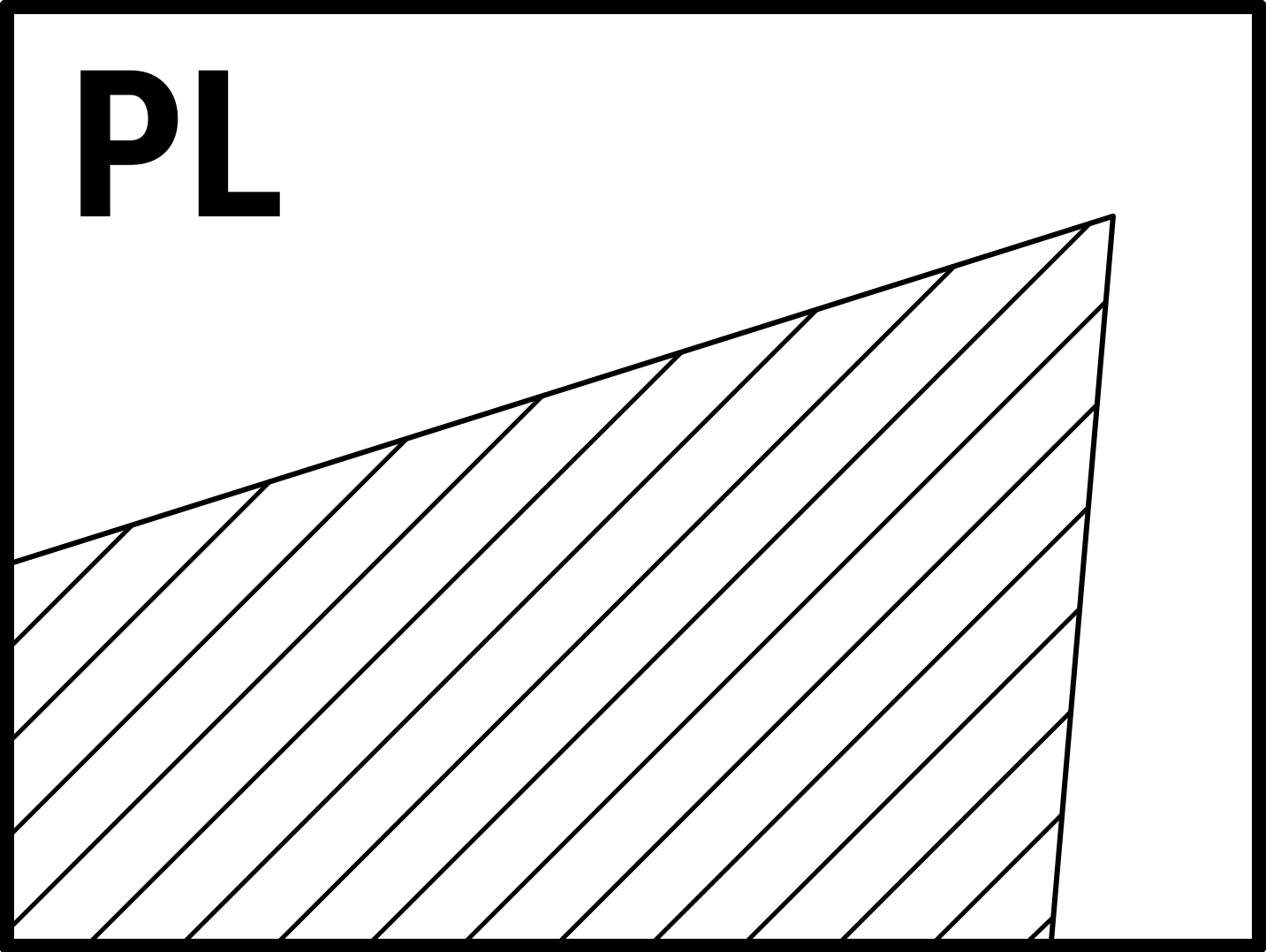
PL — Positive Cutting Land
All-round cutting geometry for ISO P, M, K, N and S materials.
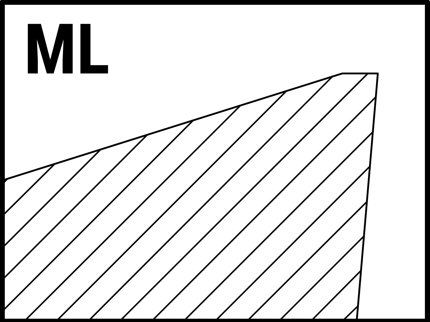
ML — Moderate Cutting Land
Moderate cutting land for ISO P, M, K, S and H materials.
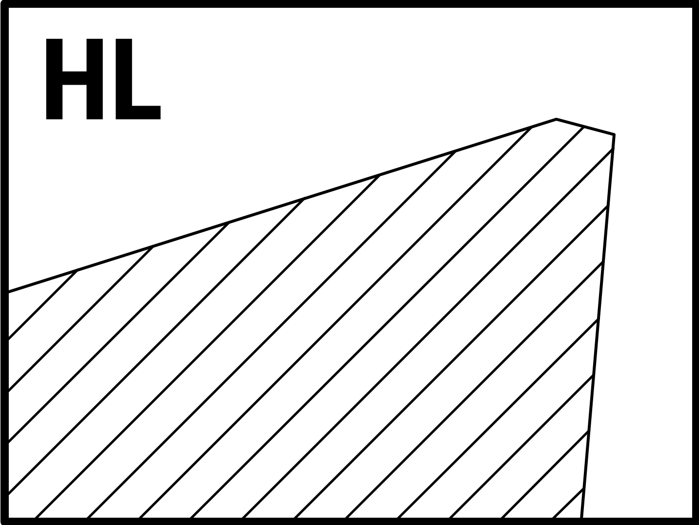
HL — Negative Cutting Land
Negative cutting land for ISO P, M, K, S and H materials.
| NOGA Code | Coating | Key Features | Typical Application | Material Examples | P | M | K | N | S | H |
|---|---|---|---|---|---|---|---|---|---|---|
| NCT | TiAlN | Thermal stability, oxidation and wear resistance. | General-purpose and high-speed machining; wet or dry. | AISI 304, 42CrMo4, gray cast iron, Ti6Al4V | ✓ | ✓ | ✓ | × | ✓ | ✓ |
| NCD | TiAlSiN | Very high hardness and oxidation resistance above 1200°C. | Demanding high-performance machining. | Inconel 718, AISI 4140, Ti6Al4V, Hastelloy | ✓ | ✓ | × | × | ✓ | ✓ |
| NCA | AlTiSiN | High hardness, thermal stability and wear resistance. | High-speed machining in extreme conditions. | AISI 316, AISI H13, Hastelloy | ✓ | ✓ | × | × | ✓ | ✓ |
| NCN | AlCrN | High oxidation resistance, toughness and abrasion resistance. | General machining in abrasive / wet conditions. | AISI 304, AISI 1045, gray cast iron, AL6061 | ✓ | ✓ | ✓ | ✓ | × | × |
| NCW | AlTiN | High hardness, wear resistance and thermal stability. | Heavy-duty and high-speed cutting; dry / abrasive conditions. | AISI 4340, M2 HSS, gray cast iron | ✓ | ✓ | ✓ | × | ✓ | × |
| NCB | TiB₂ | High conductivity and resistance to material adhesion / BUE. | High-speed machining of non-ferrous materials. | AL7075, 6061-T6, copper, magnesium alloys, SiC composites | × | × | × | ✓ | ✓ | × |
| POL | Polishing | Removes scratches / micro-defects and reduces friction. | High-speed finishing of non-ferrous materials. | AL7075, 6061-T6, copper, magnesium alloys | × | × | × | ✓ | × | × |
Frequently Asked Questions
Quick answers for the most common UBACK setup, actuation and cutting-data questions.
What applications does the UBACK system support?
UBACK UX tool-holders support USPOT inserts for CNC back counterboring and spotfacing and UCHAMF inserts for back chamfering and countersinking.
What pressure is required to actuate the UBACK insert?
The UBACK system supports coolant, emulsion or air actuation with a minimum pressure of 6 bar / 90 PSI.
What coolant should be used for interrupted UBACK cuts?
For interrupted cutting steps, use external coolant rather than internal coolant during the cutting portion of the cycle, and validate the setup for the actual geometry.
Are UCHAMF inserts standard?
UCHAMF has standard 82° and 90° insert options. Special angles can be produced for application-specific requirements.
How should UCHAMF cutting data be adjusted?
Use the UBACK cutting recommendations as starting values and reduce the recommendations by 20% when using UCHAMF inserts.
🔧 UBACK Configurator & G-Code Generator
USPOT / UCHAMF insert configurator · Tool-holder matching · CNC back counterboring & countersinking programs
Step 1: Select Insert Type
Choose the UBACK application you need. The configurator will build the exact insert designation and match the correct UX tool-holder.
Click an insert type to continue — the configurator opens automatically.
Step 2: Insert Configurator
Enter your application dimensions. All designation codes are generated in metric.
⚡ Quick Fill from Insert Designation (optional)
⚙ Configuration Parameters
📐 Technical Diagram
Step 3: Your Insert & Tool-Holder
Matched configuration based on your application. The insert series always matches the tool-holder series.
🔩 Insert
🛠 UX Tool-Holder
Step 4: Generate CNC Program
Build the back-machining cycle for your controller using the matched tool-holder and insert.
📊 Recommended Cutting Data
Generated G-Code Program
Disclaimer of Liability — CNC Programs
The CNC programs, cutting data, and 3D models generated by this tool are provided for reference and convenience only, as a starting point for process planning. They are generated automatically from the parameters entered and have not been verified for any specific machine, control, workpiece, fixture, or operating condition.
It is the sole responsibility of a qualified CNC programmer or operator to review, validate, and adapt every generated program before use — including verifying all coordinates, speeds, feeds, tool and coolant M-codes, clearances, and safety limits against the actual machine and setup. Every program must be run for the first time with appropriate caution, using reduced feed and rapid overrides, single-block execution, and a dry run without a workpiece.
To the fullest extent permitted by law, NOGA and its affiliates accept no responsibility or liability for any damage, injury, loss, or cost of any kind arising from the use of, or reliance on, the output of this tool, whether used as generated or after modification. Use of this tool constitutes acceptance of these terms.
Download 3D model
Choose what the STEP file should contain. Both options use the same datum: tool axis on Z, Z0 at the tool nose face.