
Robotic Edge Deburring Setup Example
A starting setup for deburring machined aluminium edges on a robot with UFIBER
This page shows how to put together a robot-mounted UFIBER setup: which Floating Damper, which brush and sleeve, and which starting values to use. Every value comes from NOGA MT's published UFIBER and Floating Damper data, and from a measured CNC case study on aluminium 7075.
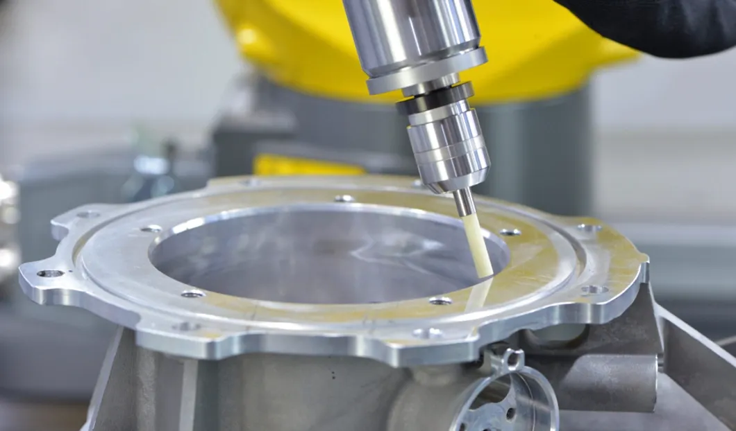
Example: edge deburring of a machined aluminium part
The task: remove milling burrs and break the edges of a machined aluminium part held in a fixture, with the brush in the robot's electric spindle.
| Item | Starting choice | Source |
|---|---|---|
| Drive | Electric spindle on the robot flange, running at 12,000 RPM or less | Floating Damper End-Type limit |
| Compliance | End-Type Floating Damper UF8851 (Ø6 mm): 6 mm stroke, about 20 N | Floating Damper specifications |
| Brush | Surface Brush Ø15 mm, shank ØDS Ø6 mm, mounted directly or in sleeve UF5515 | Surface Brush range |
| Grit | #1200 (UF1715), the grit used on aluminium 7075 in the aerospace case study; go coarser for heavier burrs | Al 7075 case study |
| Speed | 5,700–7,200 RPM; start at the low end | Surface Brush Ø15 data |
| Feed | Up to 2,000 mm/min; start well below it (the Al 7075 case ran 500 mm/min) | Surface Brush data, case study |
| Engagement (DOC) | 0.5 mm for deburring, 0.2 mm for polishing, 1.2 mm maximum | Surface Brush Ø15 data |
| Brush projection | 10 mm maximum | Surface Brush Ø15 data |
| Coolant | No through-spindle coolant through the damper | Floating Damper precautions |
Which Surface Brushes fit the robot damper
Both End-Type Floating Dampers (UF8851, UF8852) hold a Ø6 mm shank with the supplied bush fitted, or a Ø10 mm shank with the bush removed. These Surface Brush sizes match it:
Surface Brush Ø6
Mounted in sleeve UF5506 (ØDS Ø6 mm).
Surface Brush Ø15
Direct shank ØDS Ø6 mm, or sleeve UF5515 (ØDS Ø6 mm).
Surface Brush Ø25
Mounted in sleeve UF5525 (ØDS Ø10 mm).
Ø40–Ø100 mm brushes have Ø12–Ø16 mm shanks and don't fit the End-Type damper. Full dimensions are in the Surface Brush technical guide.
Programming the pass
From the Floating Damper operating guide.
Approach
Bring the brush to the edge vertically, without side contact.
Preload
Compress the damper spring and set the depth before the feed starts.
Ramp in, feed, ramp out
Arc in and out with the spindle turning for smoother engagement and fewer tool marks.
Keep it free
Don't let the tool drop into pockets or touch protruding features; the damper must move freely.
What to record in your trial
Record these so the result can be compared and repeated.
- Robot and spindle model
- Part, material and burr type (photo before)
- Damper, brush SKU, grit and sleeve
- RPM, feed, DOC and projection
- Cycle time before and after
- Edge result (photo after) and brush wear
Ready to try it on your part?
Send the drawing, material, robot and spindle model and a burr photo. NOGA MT will confirm the brush, grit, damper and starting parameters.